In the world of manufacturing, injection molding stands as a titan and there are many types of molds.
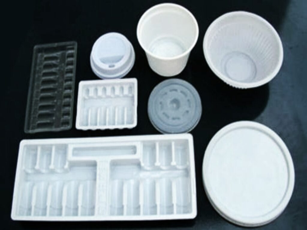
It’s the process responsible for producing millions of identical, high-precision plastic parts we encounter daily—from the tiny gears in your car’s dashboard and the shell of your smartphone to medical syringes and LEGO bricks.
But behind every flawless plastic component lies a critical, often unsung hero: the injection mold itself.
An injection mold is not a one-size-fits-all tool. It is a highly engineered, custom-built masterpiece of precision machining.
The type of mold chosen for a project is perhaps the most significant decision, as it directly impacts the part’s quality, production efficiency, per-part cost, and the manufacturer’s ability to innovate.
Understanding these differences is paramount for designers, engineers, and project managers aiming to optimize their manufacturing process and bring superior products to market.
The Foundation – How Injection Molding Works
Before we classify molds, it’s essential to understand the basic process they enable.
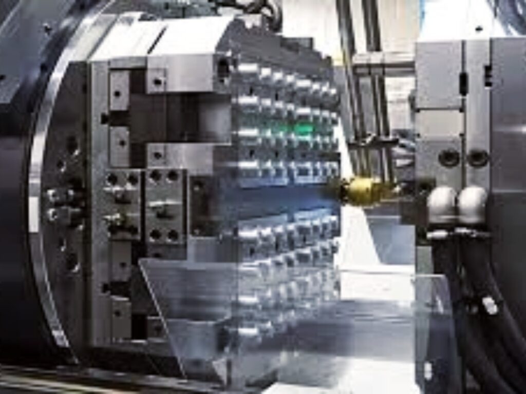
Injection molding involves injecting molten thermoplastic material under high pressure into a mold cavity. This cavity is a hollow negative of the desired part.
The material cools and solidifies within the cavity, the mold opens, and the finished part is ejected.
This cycle, which can take as little as 15-30 seconds, repeats continuously, allowing for mass production.
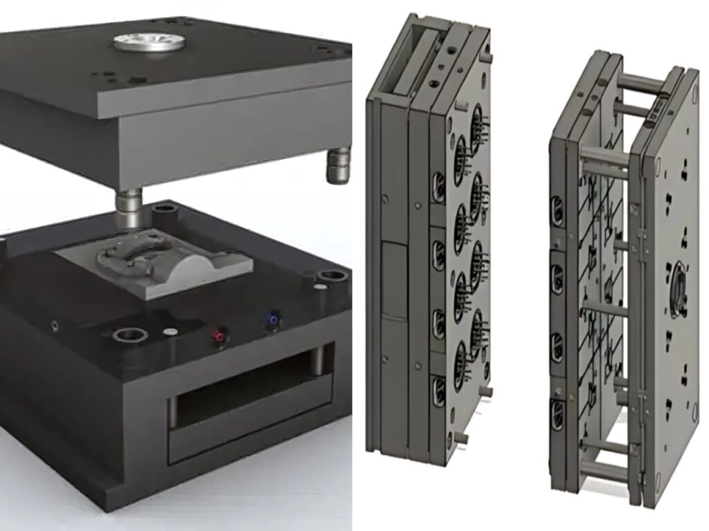
The mold itself is a complex assembly of components, typically made from hardened or pre-hardened steel or aluminum. Key components include:
- Core and Cavity: The two halves that form the external and internal shapes of the part.
- Sprue, Runners, and Gates: The channel system that delivers molten plastic from the injection machine nozzle to the cavity.
- Cooling Channels: A network of passages for circulating coolant to solidify the plastic.
- Ejection System: Pins, sleeves, or blades that push the solidified part out of the mold.
- Mold Base: The structural frame that houses all these components.
The design and configuration of these elements define the different types of molds.
The 6 Stages of the Injection Molding Cycle:
1. Clamping
Before any molten plastic can enter the mold, its two halves must be securely closed and locked.
- The moving half of the mold is pushed against the stationary half by the clamp unit.
- A toggle or hydraulic mechanism applies tremendous pressure (often hundreds of tons of force) to keep the mold tightly shut against the high injection pressure. This prevents plastic from leaking out and creating defects called “flash.”
2. Injection
The raw plastic material (usually in granular form called resin) is fed from a hopper into the barrel of the injection unit.
- Inside the barrel, a reciprocating screw turns and moves forward.
- As the screw rotates, it transports the plastic granules forward. Heater bands wrapped around the barrel melt the plastic, and the shear from the screw itself generates additional heat, creating a perfectly molten, homogenous plastic melt.
- The screw then rams forward like a plunger, injecting a precise amount of this molten plastic—called a shot—through a nozzle and into the mold’s runner system and cavities.
- This injection happens under high pressure to ensure the mold is filled completely and quickly before the plastic starts to cool.
3. Dwelling (Holdings)
After the initial injection, the screw remains forward for a brief period, maintaining pressure.
- This holding pressure packs more molten plastic into the mold to compensate for the material shrinking as it cools.
- This dwelling stage is critical for preventing sink marks (small craters) and ensuring the part is dense and has precise dimensions.
4. Cooling
The clamp unit remains closed, keeping the mold shut.
- The molten plastic inside the mold cavity begins to cool and solidify. As it cools, it takes the exact shape of the cavity.
- Cooling channels built into the mold plates constantly circulate coolant to control this process.
- Cooling time typically accounts for over half of the total cycle time. Efficient cooling is crucial for productivity and part quality.
5. Plasticizing (Recovery)
While the current part is cooling inside the mold, the injection unit prepares for the next shot.
- The screw begins to rotate and retract, drawing new plastic granules from the hopper into the barrel.
- The heat from the barrel and the mechanical shear from the screw melt this new material, preparing a fresh shot of molten plastic at the front of the screw for the next cycle.
- This happens simultaneously with cooling, optimizing the cycle time.
6. Ejection
Once the cooling time is complete and the part is solid, the mold opens.
- The clamp unit moves the moving half of the mold away from the stationary half.
- An ejection system—typically a plate with ejector pins—is activated, mechanically pushing the finished part(s) and the solidified runner system out of the mold.
- The mold then closes, and the entire cycle repeats automatically.
This entire process is highly automated and can cycle every 15 to 60 seconds, producing a new, identical part each time.
Classification by Structure – The Primary Mold Types
The most fundamental way to categorize molds is by their mechanical structure and how they open and eject parts.
This classification is crucial for determining a mold’s capability to produce parts of varying complexity.
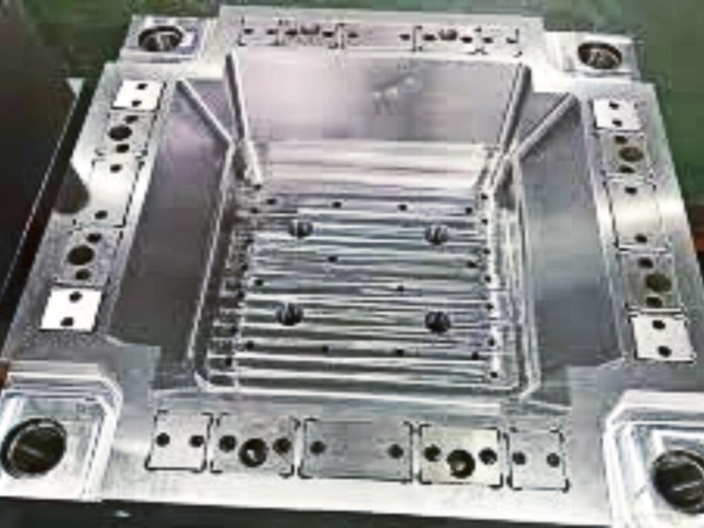
1. The Two-Platen Mold (Runner Mold)
The Two-Platen Mold is the simplest and most common type of injection mold.
Its name comes from its primary operational feature: it opens along a single parting plane, separating into two main plates—the stationary side (connected to the injection unit) and the moving side (connected to the ejection system).
How it Works:
- Molten plastic is injected through the sprue into the runners, which lead to the gates and into the cavity.
- After cooling, the mold opens. The entire contents—the finished part(s) and the solidified runner system—are pulled onto the moving side.
- The ejection system advances, pushing both the parts and the runner scrap out of the mold.
- The runner and parts are often connected and must be separated manually or by a robot after ejection.
Advantages:
- Simplicity: Straightforward design makes it easier and faster to manufacture.
- Cost-Effective: Significantly lower initial cost compared to more complex molds.
- Durability: Fewer moving parts mean less wear and easier maintenance.
- Large Part Suitability: Excellent for molding large, single items like buckets, pallets, or automotive bumpers.
Disadvantages:
- Material Waste: The entire runner system is wasted with every shot, increasing material costs.
- Secondary Operation: Requires manual or robotic separation of parts from runners, adding a step to the process.
- Gate Limitations: Gates are typically larger and leave more noticeable marks on the part.
Ideal For: Low-to-medium volume production, large parts, prototypes, and applications where material cost is not the primary driver.
2. The Three-Platen Mold
The Three-Platen Mold introduces a third plate, the runner stripper plate, between the two main plates.
This complex structure allows for automatic separation of the runner system from the part during ejection.
How it Works:
- During injection, the mold is held together as a single unit.
- When the mold opens, it separates at two different parting lines in a specific sequence.
- First Break: The runner stripper plate pulls away from the stationary side, breaking the sprue free and dragging the runner system with it.
- Second Break: The main parting line opens, allowing the finished part(s) to be released from the cavity.
- The runner system is ejected from the stripper plate, and the parts are ejected from the moving side, now completely separate.
Advantages:
- Automatic Degating: The part and runner are separated automatically within the mold cycle.
- Better Gate Location: Often uses pinpoint gates that leave very small marks, ideal for parts where aesthetics are important.
- Centered Gates: Perfect for parts that require a gate in the center, like gears or lids.
Disadvantages:
- Complexity: More complicated design and build process.
- Higher Cost: More expensive to manufacture and maintain than two-platen molds.
- Larger Footprint: Requires a taller mold and potentially a larger injection molding machine.
Ideal For: High-volume production of small components (e.g., electrical connectors, gears), parts requiring high aesthetic standards, and projects where automation is a priority.
3. Hot Runner Molds
Hot Runner Molds represent a significant technological advancement, designed to eliminate the cold runner system entirely.
They use a thermally insulated, heated manifold system to keep the plastic in a molten state throughout the delivery channels.
How it Works:
- The heated manifold, equipped with temperature-controlled probes, is installed within the mold plate.
- Molten plastic is injected from the machine nozzle into the heated manifold.
- The material stays molten as it travels through the heated channels to the nozzles, which inject it directly into the cavities.
- Since no plastic solidifies in the channels, only the part is ejected after each cycle.
Types of Hot Runners:
- Internally Heated: A heated probe runs through the center of the channel. Less common due to potential material degradation.
- Externally Heated: The entire channel is surrounded by a heater. This is the modern standard, offering excellent temperature control.
Advantages:
- Zero Runner Waste: The most significant benefit, leading to 100% material utilization and lower per-part cost.
- Improved Cycle Times: Often no runner to cool, potentially shortening the cycle.
- Enhanced Part Quality: Better pressure control, reduced shear stress, and more flexible gate positioning.
- Full Automation: Enables completely hands-free, automated production.
Disadvantages:
- Highest Cost: Significantly more expensive to design, build, and maintain.
- Complex Maintenance: Susceptible to heater and thermocouple failures; sensitive to heat-sensitive materials which can degrade and clog the system.
- Color Change Difficulty: Purging the system for a material or color change takes longer than with a cold runner mold.
Ideal For: Extremely high-volume production (e.g., consumer electronics, medical devices), applications using expensive engineering plastics, and any project where minimizing waste and maximizing automation are critical.
Classification by Cavity Number
This classification determines how many parts are produced in a single molding cycle.
- Single-Cavity Mold: Produces one part per cycle. Used for very large parts (e.g., car bumpers) or low-volume production where tooling cost must be minimized.
- Multi-Cavity Mold: Has multiple identical cavities. Produces multiple copies of the same part every cycle, drastically increasing output and reducing per-part cost. Standard for high-volume production of small items.
- Family Mold: Has multiple cavities, but each produces a different part that assemblies together (e.g., all components of a model kit). Risky because all parts must use the same material and have similar volumetric flow and cooling requirements. An imbalance can lead to some parts being perfect while others are defective.
Molds for Complex Geometries – Overcoming Undercuts
When a part has a feature that prevents its straight ejection from the mold (an undercut), specialized mold actions are required.
- Slides (or Sliders): These are moving cores that travel perpendicular to the mold’s opening direction, usually driven by angled “angle pins” as the mold opens. They retract to clear the undercut before the part is ejected. Used for external side holes or clips.
- Lifters (or Angular Lifters): These are similar to slides but are typically used for internal undercuts. They are connected to the ejector system and move at an angle, simultaneously lifting up and out to clear the undercut during ejection.
- Unscrewing Mechanisms: For parts with threaded features. After the main mold opens, a motorized or gear-driven mechanism rotates to unscrew the core from the part before ejection. This is a highly complex and expensive feature.
Choosing the Right Mold Type – A Decision Matrix
Selecting the optimal mold is a balancing act between technical requirements and economic constraints.
| Factor | Two-Platen (Cold Runner) | Three-Platen | Hot Runner |
|---|---|---|---|
| Initial Cost | Low | Medium | High |
| Material Waste | High | Medium | None |
| Cycle Time | Slower (runner must cool) | Moderate | Faster (no runner to cool) |
| Automation Level | Low (manual degating) | High (auto degating) | Very High (fully auto) |
| Part Aesthetics | Fair (larger gate marks) | Good (small gate marks) | Excellent (discreet gates) |
| Maintenance | Simple | Moderate | Complex |
| Ideal Volume | Low – Medium | Medium – High | Very High |
Key Questions to Ask:
- What is the annual volume? High volumes justify the high cost of hot runner systems.
- What is the part material? Expensive materials make hot runners more attractive to avoid waste.
- What are the aesthetic requirements? For discreet gates, consider three-platen or hot runner molds.
- What is the budget? A two-platen mold is the most economical choice for prototyping and short runs.
- Does the part have undercuts? This will necessitate slides or lifters, adding cost and complexity regardless of the primary mold type.
Conclusion: The Mold is the Masterpiece
The injection mold is far more than a simple tool; it is the embodiment of engineering ingenuity.
From the simple, robust two-platen mold to the highly efficient and complex hot runner system, each type serves a distinct purpose in the vast ecosystem of plastic manufacturing.
There is no “best” type of mold, only the best type for your specific project.
Understanding the strengths and weaknesses of each is the first and most crucial step toward a successful injection molding project.
By carefully considering part design, production volume, material selection, and cost targets in collaboration with an experienced mold designer, you can select the perfect mold type to produce high-quality parts efficiently and profitably for years to come.