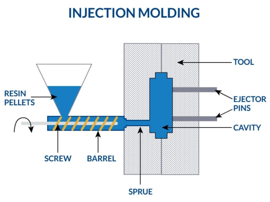
Injection molding is the undisputed champion of modern manufacturing, producing millions of identical plastic parts with incredible precision and efficiency.
From the tiny components in your smartphone to the dashboard of your car and life-saving medical devices, this process shapes the modern world.
An injection mold is a sophisticated, high-precision tool, essentially a complex cookie cutter for plastic.
It’s comprised of numerous interconnected parts, each with a critical role to play in the cycle of melting, injecting, cooling, and ejecting a finished product.
Understanding these components is crucial for designers, engineers, product managers, and procurement specialists.
It bridges the gap between a great product idea and a manufacturable, high-quality, cost-effective reality.
Next,let me introduce you to the injection molding mold parts.
The Mold Base and Its Components
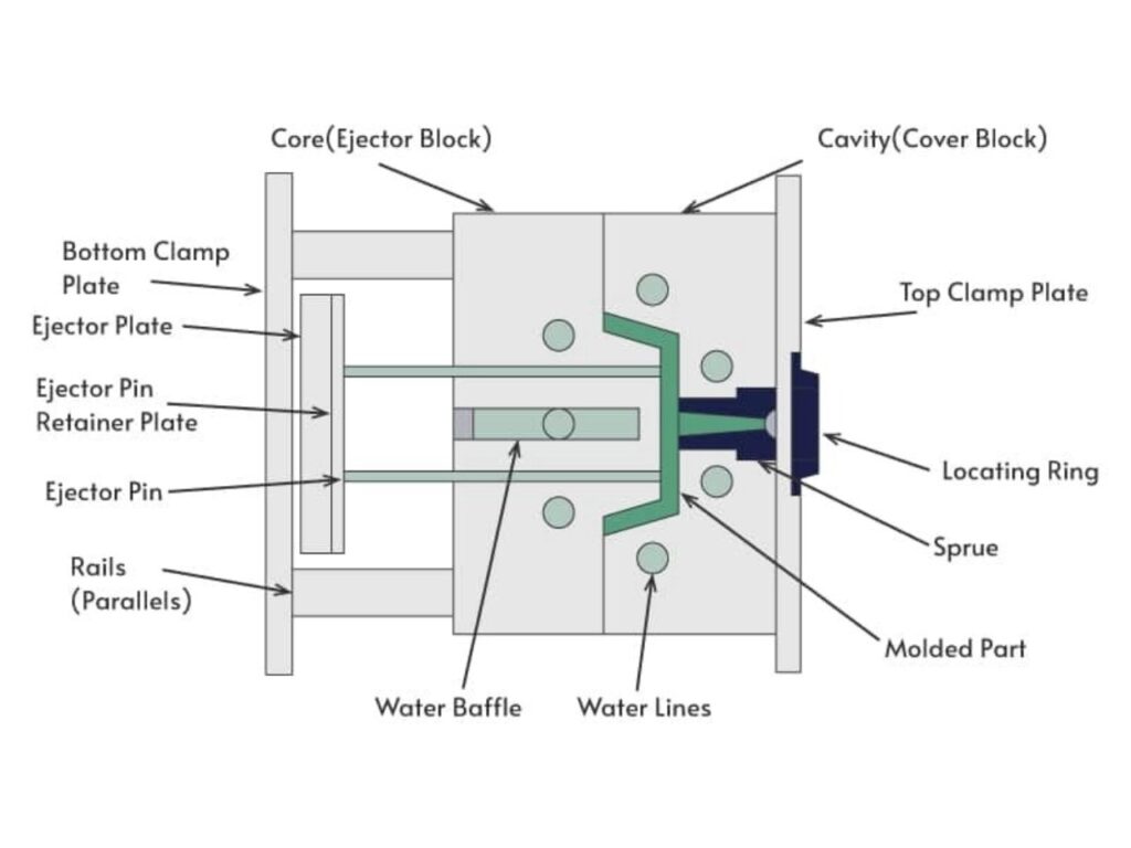
The mold base is the structural foundation of the entire tool.
It’s typically a pre-manufactured assembly of hardened steel plates that house all the other critical components.
Think of it as the chassis of a car—everything bolts onto it.
A standard mold base consists of several key plates:
- Top Clamping Plate (A): This plate is bolted directly to the stationary platen of the injection molding machine. It securely holds the fixed half of the mold in place.
- Cavity Plate (B) / “A” Plate: This plate houses the cavity halves of the mold (which form the outer shape of the part). The sprue bushing is also fitted into this plate.
- Core Plate (C) / “B” Plate: This plate holds the core halves (which form the internal features of the part). It is mounted on the moving side of the mold.
- Support Plate (D): Located behind the “B” Plate, this thick, robust plate provides essential support to the core plate. It prevents deflection and deformation caused by the immense injection pressure (often tens of thousands of psi) that pushes against the core.
- Ejector Housing (E): This section is made up of two plates: the Ejector Retainer Plate and the Ejector Plate. This housing contains the entire ejection mechanism.
- Spacer Blocks (F): These blocks are mounted on the support plate to create a gap for the ejection system to operate. They determine the space available for the ejector plates to move forward.
- Bottom Clamping Plate (G): This plate is bolted to the moving platen of the injection molding machine, securing the entire moving half of the mold.
Using a standardized mold base saves significant time and cost compared to manufacturing each plate from scratch.
Cavities and Cores
This is where the magic happens. The cavity and core are the master sculptors that give the plastic its shape.
- Cavity: The cavity is the hollow void that forms the external surface of the part. Imagine dipping a toy into a bucket of plaster; the space the toy occupied is the cavity. A single mold can have multiple cavities to produce several identical parts in one cycle (a practice called “family molding” or “multi-cavity molding”).
- Core: The core is the male component that fits into the cavity. It forms the internal surfaces and features of the part, such as holes, ribs, and other undercuts.
Cavities and cores are machined with extreme precision, often from hardened tool steels (like P20, H13) or stainless steel to withstand the abrasive, high-pressure, high-temperature environment.
They are the most critical and often the most expensive components of the mold to manufacture.
For durability and ease of repair, they are often inserted as separate blocks (called cavity inserts and core inserts) into the larger, less expensive plates of the mold base.
The Feed System
The feed system is a network of channels that meticulously guides the molten plastic from the nozzle of the injection molding machine into the cavities.
Its design is critical for part quality and material efficiency.
The feed system consists of three main parts:
- Sprue: The sprue is the primary channel that leads from the molding machine’s nozzle directly to the mold. It’s a conical channel that allows the molten plastic to flow into the mold. The Sprue Bushing is the hardened steel component that forms this channel and provides a tight seal against the machine nozzle.
- Runners: Runners are the horizontal channels that distribute the molten plastic from the sprue to the gates leading to each individual cavity. They must be designed to ensure plastic reaches all cavities simultaneously and at the same pressure and temperature. Runners can be full-round, trapezoidal, or half-round, and can be either “cold” (solidified and ejected with the part) or “hot” (thermally controlled to stay molten).
- Gates: The gate is the small, critically important entrance point through which the molten plastic finally enters the cavity. Its size, shape, and location are paramount. It must be small enough to be easily separated from the part (leaving a minimal “gate vestige”) but large enough to allow the cavity to fill properly before the plastic solidifies. Common gate types include:
- Edge Gate: Located on the part perimeter.
- Tab Gate: Used to reduce shear stress.
- Direct Sprue Gate: The sprue feeds directly into the part.
- Pin Point Gate: Leaves a very small mark, common for 3-plate molds.
- Submarine Gate (Tunnel Gate): Gates the part below the parting line, automatic degating.
The Ejection System
Once the plastic has cooled and solidified inside the cavity, it shrinks and grips tightly onto the core.
The ejection system is the mechanism that pushes the finished part off the core so it can be removed from the mold.
Key components of the ejection system include:
- Ejector Pins: The most common ejection component. These are hardened steel pins that are precision-fitted into holes in the core plate. The forward movement of the ejector plate pushes these pins against the part to nudge it free. They come in various diameters and are placed on non-cosmetic surfaces where possible.
- Ejector Plates: The ejector system is housed on two plates: the Ejector Retainer Plate (which holds the heads of the ejector pins) and the Ejector Plate (which pushes against the retainer plate). The molding machine’s ejector rod pushes against the ejector plate to activate the entire system.
- Return Pins: As the mold closes after ejection, the ejector pins must retract to their original position to avoid crashing into the cavity. Return pins (or bounce pins) protrude slightly from the ejector plate and make contact with the fixed half of the mold as it closes, forcing the ejection system to retract before the cores and cavities meet.
- Ejector Sleeves: Used to eject parts with cylindrical features, like bosses. The sleeve fits around a fixed core pin and provides a uniform pushing surface.
- Blade Ejectors: Thin, blade-like pins used to eject narrow ribs or other features where a standard round pin would not make sufficient contact.
- Stripper Plate: A plate that encircles the core, used for parts with deep, thin walls or parts that could be damaged by individual pins. It applies a uniform, simultaneous ejection force around the entire part’s perimeter.
Side-Actions (Slides & Lifters)
Many parts have features that are not parallel to the main opening direction of the mold (called “undercuts”).
These would lock the part in the mold, making ejection impossible with a simple straight pull. This is where side-actions come in.
- Slides (or Cams): Slides are components that move perpendicularly (or at an angle) to the mold’s opening direction. They are typically driven by angled guide pins (dowel pins). As the mold opens, the angled pin forces the slide to move sideways, pulling it away from the undercut. Slides are usually mounted in wear-resistant guide rails and often have a heel block to lock them in place against injection pressure.
- Lifters: Lifters perform a similar function but operate from within the core itself. They are angled components that sit inside the ejector housing. As the ejection system moves forward, the lifter is forced to move both up and out (due to its angled interface), thus clearing the undercut as it ejects the part. They are ideal for small internal undercuts.
Cooling System
The injection molding cycle has four phases: clamp close, inject, cool, and eject.
The cooling phase often takes up over half of the total cycle time. An efficient cooling system is therefore the biggest lever for profitability.
Cooling Channels: A network of precisely drilled passages (or lines) bored through the mold plates, cores, and cavities. A temperature-controlled fluid (usually water or oil) is continuously circulated through these channels to absorb heat from the molten plastic and carry it away.
Proper cooling is essential for:
- Reducing Cycle Time: Faster cooling means faster ejection and more parts per hour.
- Ensuring Part Quality: Uniform cooling prevents defects like warpage, sink marks, and internal stresses. If one section cools much faster than another, the part will warp as it tries to contract unevenly.
- Achieving Dimensional Stability: Consistent mold temperature ensures every part is identical.
Vents, Alignment, and Other Components
Several other critical components ensure the mold operates reliably and produces quality parts.
- Vents: As molten plastic rushes into the cavity, it must displace the air trapped inside. If the air cannot escape, it becomes compressed, superheats, and causes burns, incomplete filling, or short shots. Vents are very shallow machined grooves (typically 0.0005″ – 0.002″ deep) at the parting line or into ejector pins that allow air to escape while blocking plastic.
- Guide Pins (Leader Pins) and Bushings: These components ensure perfect alignment between the two halves of the mold as it closes. Misalignment would cause flash (thin sheets of plastic leaking out) and damage to the fragile cores and cavities.
- Support Pillars: These are steel columns added to the mold base to provide extra support for the support plate in areas prone to high deflection, especially in large molds.
- Fall-Away Screws: In three-plate molds, these screws control the distance the runner plate can travel during the mold opening sequence.
Why Understanding Injection Molding Mold Parts is Critical
This isn’t just technical jargon. A deep understanding of mold components directly impacts your project’s success.
- Design for Manufacturability (DFM): Designers who understand cores, slides, and ejection can create parts that are easier and cheaper to mold. They can avoid problematic undercuts, design appropriate draft angles, and specify gate locations that minimize cosmetic defects.
- Cost Control: The complexity of the mold drives its cost. The number of cavities, the need for slides/lifters, the type of steel, and the precision of the cooling system all contribute to the final price. Understanding this allows for informed trade-off decisions.
- Quality Assurance: Knowing how vents prevent burns or how cooling affects warpage empowers engineers to troubleshoot part defects effectively and communicate precisely with their mold maker.
- Efficiency and Lead Time: A well-designed mold with an efficient cooling system and reliable ejection will run faster and with less downtime, maximizing production output and minimizing cost per part.
Conclusion
An injection mold is a masterpiece of precision engineering, a complex symphony of interacting parts all working in perfect harmony.
It is far more than a block of steel; it is a system comprising the foundational mold base, the shape-defining cavity and core, the intricate feed and ejection systems, and the essential cooling and alignment components.
Whether you’re a designer sketching your first part, an engineer optimizing your production process, or a buyer searching for a new component.
Understanding “What is an Injection Mold Part” can help you make more informed decisions and create high-quality plastic parts that meet your needs.