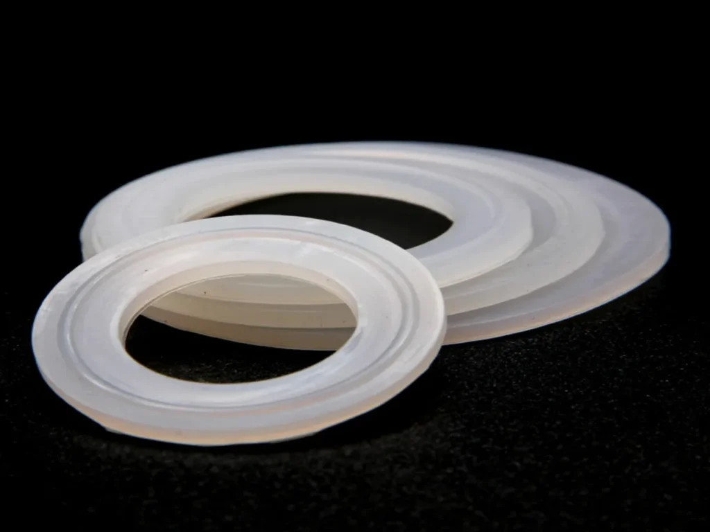
What Are Mold Seal Rings?
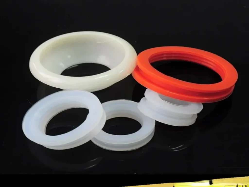
Mold sealing rings, most commonly O-rings, are specialized elastomeric seals strategically placed in injection molds to prevent fluid leakage from cooling, heating, or hydraulic systems.
These small but critical components ensure that cooling water, temperature control fluids, and hydraulic oil remain contained within their designated pathways, maintaining optimal mold performance and production efficiency.
In the simplest terms: The purpose of a seal ring (most commonly an O-ring) in a mold is to create a water-tight seal around cooling (or heating) channel connections to prevent coolant leaks.
Here’s a detailed breakdown of its purpose, types, and importance.
Core Purpose of Seal Ring
1. CONTAINMENT: Keep Fluids In Their Designated Paths
Primary Containment Function:
- Confine cooling media (water, glycol, oil) exclusively within engineered cooling channels
- Prevent external leakage that would cause production stoppages, safety hazards, and equipment damage
- Eliminate internal cross-leakage between adjacent channels that would disrupt thermal management
Why This Matters Most:
- A single leaking seal can shut down a $1M molding machine
- Internal leaks are invisible but cause defective parts through uneven cooling
- 1 drop per minute = 1 liter per day = 100+ liters per production month of wasted coolant
2. PRESSURE INTEGRITY: Maintain System Pressure Under Load
Pressure Management Requirements:
- Sustain operating pressures from vacuum (injection phase) to 100+ PSI (cooling phase)
- Resist pressure spikes during mold clamping (up to 5,000+ PSI in some applications)
- Prevent pressure decay over extended production runs (maintain constant flow rates)
Critical Consequence of Failure:
- Reduced cooling efficiency = longer cycle times = lower production output
- Inconsistent pressure = variable cooling rates = dimensional instability in parts
- Pressure loss = inadequate cavity fill = short shots and scrap parts
3. INTERFACE BRIDGING: Compensate for Imperfect Reality
The Engineering Reality:
- No two machined surfaces are perfectly flat (microscopic peaks and valleys always exist)
- Thermal expansion creates misalignment (different materials expand at different rates)
- Assembly forces distort components (clamping pressure bends plates slightly)
The Seal Ring’s Bridge Function:
- Fill microscopic voids (0.001-0.005″ gaps) between “flat” surfaces
- Absorb thermal movement (expand/compress as temperatures change)
- Distribute clamping forces (prevent point loading and damage)
- Accommodate assembly tolerances (forgive minor misalignments)
Detailed Functions and Importance:
- Prevents External Leaks: This is the most obvious function. A leak at the mold’s “water line” connections would spray coolant onto the mold, the machine, and the floor. This creates:
- Safety hazards (slippery surfaces, electrical risks).
- Production downtime for cleanup and repair.
- Water damage and potential corrosion to the mold and machine.
- Prevents Internal Cross-Leaks: More critically, sealing rings prevent coolant from leaking inside the mold assembly. For example, they seal the junction where a cooling channel drilled into the B-plate aligns with a channel in the support plate.
- Without a proper seal, coolant could escape into the gap between plates, potentially short-circuiting the cooling circuit, reducing pressure, and causing inefficient and uneven cooling. This leads to defects like warpage, sinks, and longer cycle times.
- Maintains Coolant Pressure and Flow Rate: Effective cooling requires a certain pressure and turbulent flow within the channels. A leaking seal reduces system pressure and flow, diminishing the cooling system’s efficiency and directly impacting part quality and profitability.
- Compensates for Mating Surface Imperfections: Even finely machined mold plates have microscopic grooves and imperfections. The elastic sealing ring deforms to fill these voids, creating a perfect seal that rigid metal-to-metal contact cannot achieve.
- Allows for Modularity and Service: Molds are designed to be taken apart for maintenance (cleaning, polishing, repair). Sealing rings allow for this repeated disassembly and reassembly while maintaining a reliable seal each time.
Seal Ring Common Locations in a Mold:
1. Main Parting Line Perimeter
- Location: The primary sealing groove that runs around the entire outer edge where the two mold halves (core and cavity) meet and clamp together.
- Purpose: This is the most critical seal. It prevents high-pressure steam and cooling water from leaking out of the main mold cavity into the environment. A failure here stops production.
2. Around Movable Components (Dynamic Seals)
These locations experience movement and require durable, abrasion-resistant seals.
- Ejector Pin Bushings: Each pin that pushes the finished part out of the mold has a small seal ring around its bushing to prevent steam/water from leaking along the pin shaft.
- Slide Mechanisms: For molds with moving side-cores that create undercuts, seal rings are placed where the slide meets the main mold body.
- Lifter Mechanisms: Similar to slides, for features that must lift out to release the part.
3. Around Fixed Inserts & Cores
- Location: Where separate metal blocks (e.g., for forming a handle hole or a logo) are inserted into the main mold body.
- Purpose: Seals the static interface between the insert and the mold to prevent pressure from taking the path of least resistance and leaking.
4. Utility Connections (Port Seals)
- Steam Inlet/Outlet Ports: Where steam lines connect to the mold’s internal steam chambers or distribution channels.
- Cooling Water Inlet/Outlet Ports: Where hoses connect to the mold’s internal cooling channels.
- Air Vent Plugs/Valves: At the ends of vent lines.
5. Between Mold Plates (Stack Molds or Multi-Plate Molds)
- Location: In more complex mold designs with multiple layers of plates (e.g., for family molds or multi-material molds).
- Purpose: Seals the interfaces between these plates to isolate different pressure zones or cooling circuits.
Types of Seal Rings Used in Molds
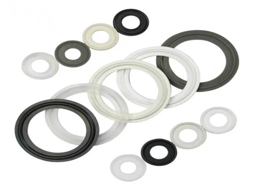
By Cross-Sectional Shape & Design
| Type | Description & Image | Primary Use Case |
|---|---|---|
| Standard O-Ring (Round Cross-Section) | Circular cross-section. The most common and versatile type. | Static Seals: Main parting line, around fixed inserts, utility ports. Cost-effective and reliable for most non-moving interfaces. |
| D-Ring / Piston Ring (D-Shaped or Rectangular) | Flat on one side, rounded or flat on the other. Provides a larger sealing surface. | Static & Light Dynamic Seals: Often used on the main parting line where a flat mold surface contacts a groove. Resists extrusion better than O-rings at very high pressures. |
| X-Ring (Quad Ring) | Double-lobed, X-shaped cross-section. Creates two sealing points instead of one. | Dynamic Seals: Excellent for ejector pins, slides, and lifters. Reduced friction and rolling compared to O-rings, leading to longer life in moving applications. |
| Square-Ring / Gland Ring | Square or rectangular cross-section. | High-Pressure Static Seals: Used where very high pressure could cause an O-ring to extrude into the gap. Often made of harder compound. |
| U-Cup / Lip Seal | U-shaped cross-section with a flexible lip. | Dynamic Seals for Cylinders: Common in hydraulic cylinders for mold clamping units, not typically inside the mold cavity itself. |
By Material (For EPS Molding Environment)
| Material | Key Properties | Best For |
|---|---|---|
| Silicone (VMQ) | Excellent high-temp flexibility (up to 230°C/450°F), good compression set. Fair abrasion resistance. | General-purpose static seals in steam environments. Common for main parting line seals. |
| Fluorocarbon (FKM/Viton®) | Superior chemical & steam resistance, good high-temp performance (up to 200°C/390°F). Better abrasion resistance than silicone. | Dynamic seals (ejector pins, slides) and high-pressure static seals. Industry standard for demanding mold applications. |
| Perfluoroelastomer (FFKM/Kalrez®) | Exceptional chemical/steam resistance and thermal stability (up to 315°C/600°F). Extremely low compression set. | Extreme service where standard seals fail. Very expensive, used for critical seals in high-cycle or corrosive environments. |
| Ethylene Propylene (EPDM) | Good steam and hot water resistance, excellent compression set. Poor resistance to oils and hydrocarbons. | Cooling water circuit seals specifically. Not recommended for areas exposed to steam or mold release agents. |
| Nitrile (NBR/Buna-N) | Good abrasion resistance and compression set. Moderate temperature limit (~120°C/250°F). Poor steam resistance. | Low-cost, general-purpose seals in non-steam areas (e.g., auxiliary equipment). Not ideal for core mold cavity seals. |
By Function & Location
- Static Seals: For joints with no relative movement (e.g., parting line, plate joints). O-Rings and D-Rings are most common.
- Dynamic Seals: For joints with movement (e.g., ejector pins, cores, slides). X-Rings and specialized FKM O-Rings are preferred for low friction and long life.
- Port Seals: For hydraulic, steam, and water connections. Often small, high-durometer O-rings or flat gaskets.
The Hierarchy of Seal Ring Functions
Material Selection
The material must survive the specific operating conditions.
- Temperature Resistance: Must withstand continuous steam temperatures (100-120°C / 212-250°F) and peak temperatures during cleaning or purges. Silicone (VMQ) and Fluorocarbon (FKM/Viton®) are standards.
- Media Compatibility: Must be chemically inert to:
- Saturated Steam
- Cooling Water (may contain treatment chemicals)
- Minor Mold Release Agents
- Cleaning Solvents
- Compression Set Resistance: The material must return to its original shape after long periods under compression. A high compression set leads to permanent deformation and leakage. FKM typically outperforms silicone here.
- Abrasion & Tear Resistance: Critical for dynamic seals on ejector pins and slides. The material must resist shaving and cutting from repeated movement against metal edges.
Groove Design
The groove must be machined to exact specifications to allow the seal to function properly.
- Groove Volume vs. Seal Volume: The groove must be slightly larger than the seal’s cross-sectional volume (typically a 70-90% fill ratio). This allows space for the seal to deform under compression without being overstressed, which causes premature failure.
- Surface Finish: Groove walls must have a smooth finish (~0.8 μm Ra or better) to prevent the seal from abrading during installation or compression.
- Clearance Gap: The gap between the metal mating surfaces must be smaller than the compressed seal. This prevents the seal from being extruded under high pressure into the gap, which would tear it apart.
Squeeze
The seal must be compressed by a precise percentage of its cross-sectional diameter.
- Typical Static Seal Squeeze:15-30%. This provides enough sealing force without excessive stress.
- Too little (<10%) → Risk of leakage.
- Too much (>30%) → High friction, rapid wear, difficult assembly/disassembly, and accelerated compression set.
- Dynamic Seal Squeeze: Generally lower (10-20%) to minimize friction and heat buildup from movement.
Hardness
Measured on the Shore A scale, it balances sealing force and flexibility.
- Softer (60-70 Shore A): Better conforms to uneven surfaces, good for low-pressure static seals. More prone to extrusion.
- Medium (70-80 Shore A): The most common range. Good balance of sealing and extrusion resistance for general mold applications.
- Hard (80-90 Shore A): Used for high-pressure applications (e.g., main parting line on large molds) and dynamic seals to resist extrusion and abrasion. Requires excellent groove finish and alignment.
Thermal Expansion
The seal material will expand when heated by steam.
- Consideration: The groove design must account for this expansion. If the groove is too tight, thermal expansion can over-compress the seal, drastically increasing stress and causing failure.
- Material Choice: FKM has a lower coefficient of thermal expansion than silicone, making its behavior more predictable under the rapid thermal cycling of an EPS mold.
Assembly & Maintenance
- Ease of Installation: Sharp edges on the mold or groove must be chamfered to guide the seal and prevent cutting during installation.
- Accessibility: Seal locations should allow for inspection and replacement without completely disassembling the mold, minimizing downtime.
- Lubrication: Use a compatible, high-temperature lubricant (e.g., silicone-based) during installation to prevent pinching and reduce initial friction.
The Single Most Important Metric: Leak Rate
Acceptable Performance:
- Static Seals: Zero visible leakage over 24 hours of operation
- Dynamic Seals: < 1 drop per hour under operating conditions
- Internal Seals: No pressure drop > 5% over 1,000 cycles
Failure Threshold:
- Any visible external leakage = Immediate action required
- Cooling efficiency drop > 10% = Investigate internal leakage
- Pressure decay > 15% = Seal replacement needed
Key Design Considerations of Seal Ring
- Groove Design: The groove that houses the O-ring must be machined to precise standards (depth, width, surface finish) according to industry specifications (e.g., AS568 standard). A poorly machined groove will cause seal failure.
- Compression: The O-ring must be compressed by a specific percentage (typically 15-30%) to function properly. Too little compression causes leaks; too much causes excessive wear and failure.
- Material Compatibility: The ring material must be compatible with the coolant type (water, glycol, oil) and temperature.
- Prevent Pinching: Grooves are often designed with lead-in chamfers to prevent the O-ring from being sheared or pinched during mold assembly.
Consequences of a Failed Seal Ring:
- Coolant leaks (external or internal).
- Uneven part cooling, leading to warpage, dimensional instability, or sink marks.
- Increased cycle times to compensate for poor cooling.
- Corrosion inside the mold from stagnant water or leaks.
- Unplanned production stops and maintenance costs.
Specialized Applications of Seal Ring
High-Pressure Molds
For applications exceeding 500 PSI:
- Use harder durometer O-rings (80-90 Shore A)
- Always install PTFE backup rings
- Consider quad rings or X-rings for better extrusion resistance
- Implement pressure testing after assembly
High-Temperature Applications
For molds running above 150°C:
- Select FKM or FFKM materials
- Consider metal-encapsulated seals for extreme conditions
- Implement cooling near seal locations when possible
- Monitor compression set more frequently
Food-Grade and Medical Molds
- Use FDA-approved materials (platinum-cured silicone, EPDM)
- Implement cleanroom installation procedures
- Consider permanent lubrication options
- Document material certifications for compliance
Conclusion
While small and inexpensive, the seal ring is a critical component in injection mold functionality. It is the guardian of the cooling system’s integrity.
Proper selection, installation, and maintenance of these seals are essential for achieving consistent part quality, efficient production cycles, and reliable, leak-free mold operation.
A failed O-ring can shut down a mold just as effectively as a broken core pin.