By using 3D Printing Molds for Casting, you can bypass the expensive and time-consuming traditional mold-making process, enabling rapid prototyping, design iteration, and even low-volume production at a fraction of the cost.
The integration of 3D printing technology with traditional casting processes has revolutionized how manufacturers, hobbyists, and designers create metal and plastic parts.
Two Main Approaches to 3D-Printed Casting Molds
Approach A: 3D-Printed Sacrificial Pattern
In this approach, you 3D print a pattern that serves as a positive model of your desired part. This pattern is then used to create a mold around it, after which the pattern is removed—typically by melting, burning, or dissolving—leaving a cavity that exactly replicates the pattern’s shape .
Key characteristic: The 3D-printed pattern is consumed or destroyed during the mold-making process.
Also known as: Lost-wax casting (when using wax patterns), investment casting, sacrificial pattern method, indirect 3D printing for casting.
Approach B: 3D-Printed Direct Mold
In this approach, you 3D print the mold itself—the negative cavity that will receive the casting material. The printed mold is used directly for casting, typically assembled, filled with casting material, and then opened to reveal the finished part .
Key characteristic: The 3D-printed object is the mold (tooling), which may be reusable or disposable depending on the material and casting process.
Also known as: Direct mold printing, rapid tooling, 3D-printed tooling, direct patternless casting.
Approach A: 3D-Printed Sacrificial Patterns
How It Works
The sacrificial pattern method follows a sequence similar to traditional investment casting, but with a 3D-printed pattern replacing the traditional wax pattern:
- Design Phase: Create a 3D CAD model of your desired final part
- Printing Phase: 3D print the pattern using a material designed to be completely removed later
- Pattern Preparation: Attach sprue, gates, and runners (or print them integrated)
- Mold Creation: Build a mold around the pattern (typically ceramic shell for metal casting)
- Pattern Removal: Eliminate the pattern through burnout, melting, or dissolution
- Casting: Pour molten material into the resulting cavity
- Finishing: Break away mold, cut off sprues, finish the part
Materials for Sacrificial Patterns
The choice of material is critical—it must be printable yet completely removable without damaging the mold or leaving residue:
| Material | Printing Technology | Removal Method | Best For |
|---|---|---|---|
| Castable Wax Resin | SLA/DLP | Burnout (650-750°C) | Jewelry, small precision parts |
| Standard Wax Filaments | FDM | Melt-out (oven) | Larger patterns, lower detail |
| Investment Casting Resin | SLA/DLP | Burnout (<0.02% ash) | High-quality metal castings |
| PLA | FDM | Burnout (difficult, high ash) | Not recommended—leaves residue |
| ABS | FDM | Solvent dissolution (acetone) | Limited use, safety concerns |
| PVA | FDM | Water dissolution | Simple geometries, educational |
| Acrylic-based resins | SLA/DLP | Burnout | General investment casting |
Critical Note: Standard PLA and ABS are generally not suitable for investment casting because they leave ash residues and expand during burnout, potentially cracking the ceramic shell .
Printing Considerations for Sacrificial Patterns
Wall Thickness:
- Aim for 0.5-1.0 mm wall thickness for most patterns
- Thicker walls (>2 mm) can crack ceramic shells during burnout
- Very thin walls (<0.5 mm) may be fragile during handling
Internal Support:
- For hollow patterns, design internal lattice structures (typically 0.5-1.0 mm struts spaced 3 mm apart)
- Lattice supports thin walls while allowing drainage of uncured resin
- Ensure drain holes (2 mm+) are included for resin escape
Surface Finish:
- Layer lines can transfer to the final casting
- Use the smallest practical layer height (25-50 µm for resin, 100 µm for FDM)
- Consider surface finishing techniques (vapor smoothing, sanding) for critical applications
Orientation:
- Angle patterns 30-45 degrees to minimize supports
- Position drain holes at the lowest point for complete drainage
The Burnout Process
For investment casting with resin patterns, the burnout cycle is meticulously controlled:
Typical Burnout Schedule:
- Ramp 1: Room temperature to 150°C (slow ramp, hold 1-2 hours) — remove water, initial decomposition
- Ramp 2: 150°C to 400°C (slow ramp, hold 2-3 hours) — pattern vaporization begins
- Ramp 3: 400°C to 750°C (moderate ramp, hold 2-4 hours) — complete burnout, residual carbon oxidation
- Cooling: Controlled cool to casting temperature
Key Requirements:
- <0.02% ash residue — ensures clean metal
- No rapid expansion — prevents shell cracking
- Complete burnout — eliminates carbon defects in final casting
Advantages of the Sacrificial Pattern Approach
Unlimited design freedom: Complex internal geometries, undercuts, hollow structures possible
Excellent surface finish: Can achieve cast surface quality <100 microinches
No draft angles required: Pattern doesn’t need to be removed from mold mechanically
Thin walls possible: Can cast walls as thin as 0.3-0.5 mm
Wide material compatibility: Works with virtually any castable metal
No tooling investment: Each pattern is printed individually
Limitations of the Sacrificial Pattern Approach
Single-use only: Each casting requires a new printed pattern
Time-consuming: Burnout cycle adds hours to process
Size limitations: Very large patterns difficult to handle and burnout uniformly
Material waste: Pattern material is consumed in every cycle
Process complexity: Multiple steps, each requiring expertise
Higher per-part cost for volume: Not economical for high-volume production
Ideal Applications
- Jewelry manufacturing: Intricate rings, pendants, custom designs
- Dental and medical: Crowns, implants, surgical guides
- Art and sculpture: Bronze statues, artistic pieces
- Prototyping metal parts: Functional metal prototypes
- Aerospace components: Small, complex turbine blades, brackets
- Custom hardware: One-off decorative hardware, custom fittings
Approach B: 3D-Printed Direct Molds
How It Works
The direct mold method bypasses pattern-making entirely, printing the mold tooling itself:
- Design Phase: Create CAD model of the mold—typically split along a parting line, with cavity/core, sprue, runners, and vents
- Printing Phase: 3D print the mold components using suitable material
- Post-Processing: Clean, cure (if resin), and finish mold surfaces
- Assembly: Align mold halves using registration features
- Casting: Pour casting material into the assembled mold
- Demolding: Open mold, remove casting
- Reuse (if applicable): Clean mold and repeat for additional castings
Materials for Direct Molds
The material choice depends on the casting process and desired mold life:
| Material | Printing Technology | Max Temperature | Mold Life | Best For |
|---|---|---|---|---|
| High-Temperature Resin | SLA/DLP | 220-280°C | 10-100 cycles | Low-temp metals (pewter, zinc), wax, resin |
| Standard Resin | SLA/DLP | 80-120°C | 1-10 cycles | Silicone molds, plaster, low-temp casting |
| PA12 (Nylon) | MJF/SLS | 150-180°C | 50-500 cycles | Sand casting patterns, wax injection |
| PA12-GF (Glass-filled) | MJF/SLS | 180-200°C | 100-1000+ cycles | Sand casting patterns, durable tooling |
| ULTEM/PEI | FDM (high-temp) | 200-215°C | 50-200 cycles | High-temp applications |
| PEEK | FDM (specialized) | 240-260°C | 100-500 cycles | High-performance tooling |
| Sand/Binder | Binder Jetting | >1000°C | Single-use | Direct sand molds for metal casting |
| Ceramic | Stereolithography | >1000°C | Single-use | Investment casting shells |
Design Considerations for Direct Molds
Mold Design Essentials:
- Parting line: Plan where mold splits for casting removal
- Draft angles: Include 1-3 degrees on vertical surfaces for easy ejection
- Wall thickness: Minimum 2-3 mm for structural integrity; thicker for heat dissipation
- Sprue and runners: Design material entry channels with appropriate geometry
- Vents: Include air escape channels to prevent trapped gas
- Registration features: Pins and matching recesses ensure perfect alignment
- Ejection features: Consider how to remove the casting without damage
For Metal Casting Molds:
- Account for metal shrinkage (typically 1-3%)
- Design cooling channels if needed
- Consider thermal expansion of mold material
- Ensure adequate venting for gas escape
For Sand Casting Patterns (used to make sand molds):
- Add draft angles (1-3° minimum)
- Include fillets at sharp corners (prevents sand erosion)
- Consider pattern wear—glass-filled nylon extends life
- Design for pattern extraction from sand
Printing Strategies for Direct Molds
Orientation:
- Orient mold halves with critical surfaces facing up for best finish
- Position parting line surfaces vertically or at angle to minimize supports
- Consider orientation that minimizes support on cavity surfaces
Layer Height:
- 50-100 µm for detailed mold cavities
- 100-200 µm for larger molds or patterns
Infill:
- 100% infill for molds subjected to pressure
- Solid shells with sparse infill acceptable for low-pressure casting (silicone, resin)
Surface Finish:
- Every layer line on cavity surface transfers to cast part
- Consider post-processing (sanding, coating) for critical surfaces
- For sand casting patterns, smoother surfaces improve sand flow and mold quality
Advantages of the Direct Mold Approach
Speed: From CAD to first casting in hours or days, not weeks
Pattern-less: Eliminates pattern-making step entirely
Reusable: Depending on material, molds can produce multiple castings
Complex tooling: Conformal cooling channels, complex venting possible
Cost-effective for short runs: No expensive steel tooling required
Design iteration: Easy to modify digital file and reprint
Reduced skill barrier: Less traditional toolmaking expertise required
Limitations of the Direct Mold Approach
Limited mold life: Plastic molds wear faster than metal tooling
Temperature constraints: Most printable materials have upper temperature limits
Surface finish: Layer lines may transfer to cast parts
Size limitations: Build volume of 3D printer limits mold size
Pressure limitations: May not withstand high injection pressures
Draft required: Parts must eject from mold (unlike sacrificial method)
Ideal Applications
- Sand casting patterns: Durable patterns for creating sand molds
- Low-volume metal casting: Pewter, zinc, aluminum (with high-temp resins)
- Silicone mold masters: 3D-printed patterns for creating flexible silicone molds
- Wax injection tooling: Molds for creating wax patterns (investment casting)
- Prototype tooling: Bridge tooling for pilot production
- Custom casting: One-off or short-run parts
- Educational settings: Teaching casting principles without expensive tooling
Head-to-Head Comparison
| Factor | Approach A: Sacrificial Pattern | Approach B: Direct Mold |
|---|---|---|
| What is 3D printed? | The pattern (positive) | The mold (negative) |
| Pattern required? | Yes (printed) | No |
| Mold required? | Yes (ceramic/sand) | Yes (printed) |
| Design freedom | Unlimited (no draft, undercuts) | Limited by mold ejection |
| Draft angles needed? | No | Yes (1-3°) |
| Surface finish | Excellent (smooth patterns) | Variable (layer lines) |
| Mold life | N/A (single use) | 1-1000+ cycles |
| Per-part cost (low volume) | Moderate to high | Low to moderate |
| Per-part cost (high volume) | Very high | Moderate |
| Lead time to first part | Days (printing + burnout) | Hours (printing only) |
| Maximum part complexity | Very high | Moderate |
| Internal features | Yes (hollow, lattice) | Limited by draft |
| Metal compatibility | All castable metals | Limited by mold temp |
| Equipment needed | Furnace, burnout oven | Basic casting setup |
| Skill level required | Higher (multiple steps) | Moderate |
Why Choose 3D Printing Molds for Casting Over Traditional Methods?
3D printing offers compelling advantages for mold-making :
| Factor | 3D-Printed Molds | Traditional Molds (CNC/Wood) |
|---|---|---|
| Design Complexity | Unlimited—complex geometries, undercuts, conformal channels | Limited by tooling constraints |
| Lead Time | Hours to days | Weeks to months |
| Cost for Small Batches | Very low | High (tooling amortization) |
| Design Iterations | Easy and cheap—modify digital file, reprint | Expensive and time-consuming |
| Skill Required | CAD design + basic 3D printing knowledge | Specialized toolmaking expertise |
| Durability | Lower (plastic molds) to good (specialty resins) | Excellent (steel/aluminum) |
Key Insight: 3D-printed molds excel for prototyping, custom one-offs, and low-volume production (typically 10-1000 parts). For mass production (100,000+ parts), traditional steel molds remain essential .
Step-by-Step Process for Creating 3D Printing Molds for Casting
Before You Begin: Essential Prerequisites
Required Equipment and Materials
| Category | Sacrificial Pattern Method | Direct Mold Method |
|---|---|---|
| 3D Printer | SLA/DLP resin printer (preferred) or high-resolution FDM | SLA/DLP, MJF, SLS, or high-temp FDM |
| Design Software | CAD program (Fusion 360, SolidWorks, Blender) | CAD program with mold design features |
| Printing Materials | Castable wax/resin, investment casting resin | High-temp resin, glass-filled nylon, ceramic |
| Casting Equipment | Burnout furnace, casting machine, crucible | Basic casting setup (depends on material) |
| Safety Gear | PPE: gloves, respirator, safety glasses, heat protection | PPE appropriate for casting material |
| Post-Processing | Solvent (IPA), UV curing station, sprue cutter | Sanding tools, sealing materials |
Workspace Requirements
- Well-ventilated area for printing and casting
- Heat-resistant surface for furnace operations
- Proper storage for flammable materials
- Fire extinguisher rated for metal fires
- First aid kit and emergency protocols
Approach A – Sacrificial Pattern Method
This method is ideal for complex geometries, jewelry, and parts requiring excellent surface finish.
Step 1: Design Your Pattern
Create the 3D Model
- Use CAD software to design your final desired part
- Consider the following design rules:
- Wall thickness: 0.5-1.0 mm ideal (thin enough for burnout, thick enough for handling)
- Avoid sharp corners: Add fillets (0.5 mm minimum radius)
- Include sprue: Design an integrated sprue or plan to attach one later
- Drain holes: For hollow patterns, include 2 mm+ holes for uncured resin drainage
Scale for Shrinkage
- Metal shrinks as it cools (typically 1-3% depending on alloy)
- Apply shrinkage compensation in CAD:
- Aluminum: +1.3%
- Bronze: +1.5%
- Gold/Silver: +1.2%
- Steel: +2.0%
- Consult your metal supplier for exact values
Orient for Printing
- Angle the model 30-45 degrees to minimize supports
- Position drain holes at the lowest point
- Keep critical surfaces away from supports
Print the Pattern
Select Material
| Material | Printer Type | Properties | Best For |
|---|---|---|---|
| Castable Wax Resin | SLA/DLP | <0.02% ash, burns cleanly | Jewelry, precision parts |
| Investment Casting Resin | SLA/DLP | High detail, clean burnout | General metal casting |
| Standard Wax Filament | FDM | Lower detail, melt-out | Larger patterns, prototypes |
| NOT RECOMMENDED | Any | PLA, ABS leave ash/residue | Avoid for quality casting |
Configure Print Settings
- Layer height: 25-50 µm for resin (smoother surface = better cast finish)
- Support settings:
- Use light touch points for easy removal
- Avoid supports on critical surfaces when possible
- Hollow vs. Solid: Hollow patterns with lattice supports save material and improve burnout
Print and Post-Process
- After printing, wash thoroughly in IPA (isopropyl alcohol) per resin specifications
- Use compressed air to clear internal cavities
- Remove supports carefully with flush cutters
- Post-cure according to material requirements (UV and/or heat)
Pro Tip: Clean, hollow patterns with all uncured resin removed prevent “explosions” during burnout.
Prepare the Pattern for Investment
Attach Sprue System
- Create sprue, runners, and pouring cup (can be printed separately or integrated)
- Attach using:
- Wax welding iron (for wax patterns)
- Cyanoacrylate (CA) glue + accelerator
- UV-cured resin (careful with shrinkage)
- Ensure smooth transitions to prevent turbulence during pouring
3.2 Clean and Inspect
- Remove all dust and debris
- Check for any cracks or defects
- Weigh the pattern (helps calculate metal needed)
Step 4: Create the Investment Mold
Select Investment Material
| Material | Application | Mix Ratio | Burnout Temp |
|---|---|---|---|
| Phosphate-bonded | High-temp alloys (steel, cobalt) | 100:35-40 (powder:liquid) | 800-1000°C |
| Gypsum-bonded | Non-ferrous (gold, silver, bronze) | 100:40 | 650-730°C |
| Silica sol | Ceramic shell (multiple coats) | N/A (slurry) | 800-900°C |
Investing Process
- Select flask with adequate clearance (6-10 mm around pattern)
- Seal flask base with tape
- Mix investment according to manufacturer specifications
- Apply vacuum to remove air bubbles (30-60 seconds)
- Pour investment carefully to avoid trapping air
- Place under vacuum for 1-2 minutes to complete de-airing
- Allow to set (typically 1-2 hours)
Ceramic Shell Method
- Dip pattern in primary slurry (fine ceramic)
- Apply fine stucco (sand)
- Dry thoroughly
- Repeat 5-8 times for required thickness
- Final seal coat
Step 5: Burnout
Prepare for Burnout
- Remove flask base and tape
- Place flask in cold furnace (preheat can crack investment)
- Ensure adequate ventilation (burnout produces fumes)
Critical Check: The flask should reach target temperature before casting to ensure complete burnout and proper mold temperature.
Step 6: Casting
Prepare Metal
- Calculate metal needed (pattern weight × metal density × 1.2 for sprue)
- Preheat metal in crucible to recommended temperature:
- Aluminum: 700-750°C
- Bronze: 1100-1200°C
- Silver: 950-1000°C
- Gold: 1050-1150°C
- Steel: 1550-1650°C
Casting Methods
| Method | Equipment | Best For |
|---|---|---|
| Centrifugal | Centrifugal casting machine | Jewelry, small parts |
| Vacuum assist | Vacuum casting machine | Thin sections, intricate details |
| Gravity pour | Simple ladle + flask | Larger parts, less detail |
| Pressure cast | Pressure casting machine | Densification, porosity reduction |
Pouring Process
- Remove flask from furnace (work quickly)
- Position in casting machine
- Pour molten metal immediately
- Activate casting mechanism
- Allow to cool completely (time depends on size)
Step 7: Demolding and Finishing
Quench
- Some investments require water quenching for easy breakdown
- Check investment specifications—some crack on contact with water
Remove Investment
- Break away investment using:
- Hammer and chisel (careful with casting)
- Water blasting
- Vibratory finisher
Cut Off Sprue
- Use jewelry saw, cutoff wheel, or abrasive cutter
- Leave small stub for final grinding
Finish the Casting
- Grind sprue stub flush
- Sand/Polish as required
- Heat treat if necessary
- Patina or plate if desired
Part 2: Approach B – Direct Mold Method
This method is ideal for simpler geometries, multiple copies, and faster turnaround.
Step 1: Design the Mold
Part Analysis
- Examine your final part for:
- Draft angles: 1-3° minimum on vertical surfaces
- Undercuts: Can they be managed with split molds?
- Parting line: Where should the mold separate?
- Shrinkage: Account for material contraction
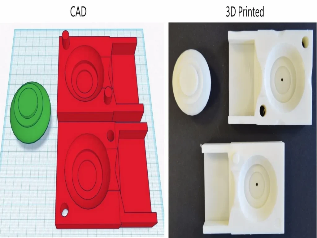
Mold Design in CAD
- Create a bounding box around your part (add 10-20 mm clearance)
- Position part inside box, oriented for best mold fill
- Use CAD tools to subtract part from box → creates cavity
- Split the box along your planned parting line
- Add alignment features:
- Registration pins (male) and matching holes (female)
- Lip and groove around perimeter
- Add pouring system:
- Sprue: Tapered entry channel
- Runner: Distribution channels
- Gates: Where material enters cavity
- Vents: Air escape channels (0.1-0.3 mm deep on parting line)
Mold Design Checklist
- Minimum wall thickness 2-3 mm
- Draft angles 1-3° minimum
- Registration features with 0.1-0.2 mm clearance
- Sprue diameter 3-10 mm (tapered)
- Vents at high points of cavity
- Fillets at all internal corners (0.5 mm min)
- Ejection features (if needed)
Step 2: Select Mold Material
| Casting Material | Recommended Mold Material | Printer Tech | Mold Life |
|---|---|---|---|
| Wax (for investment patterns) | Standard resin, PA12 | SLA/MJF | 100-1000 cycles |
| Silicone (for molding) | Standard resin, ABS-like | SLA/FDM | 10-50 cycles |
| Resin (urethane, epoxy) | High-temp resin, PA12-GF | SLA/MJF | 10-100 cycles |
| Low-melt metals (pewter, zinc) | High-temp resin (280°C capable) | SLA | 10-50 cycles |
| Aluminum (gravity pour) | Glass-filled nylon, ceramic | MJF/SLS | 1-10 cycles |
| Sand (for sand casting) | PA12-GF, ABS | FDM/MJF | 100-1000+ cycles |
Step 3: Print the Mold
Orient for Printing
- Position mold halves with cavity facing up for best surface finish
- Place parting line surfaces vertically or at 45° to minimize supports
- Consider printing with sprue channels oriented vertically
Print Settings
- Layer height: 50-100 µm for cavity surfaces
- Infill: 100% for molds under pressure; solid shells with 20-30% infill for low-pressure
- Supports: Minimize on cavity surfaces; use support blockers in critical areas
Post-Processing
- Remove supports carefully
- Clean and cure (for resin)
- Sand mating surfaces for perfect alignment
- Smooth cavity if needed (finer grits for better surface finish)
- Apply mold release agent before first use
Step 4: Assemble and Prepare
Test Fit
- Assemble mold halves without casting material
- Check alignment—pins should engage smoothly
- Verify cavity registration
- Check sprue and vent alignment
Seal
- For porous prints (FDM), apply:
- Epoxy sealer
- Cyanoacrylate (thin CA) brushed on surfaces
- Paint-on mold coating
- For resin prints, ensure complete curing
Apply Mold Release
| Casting Material | Recommended Release Agent |
|---|---|
| Wax | Silicone spray, soap solution |
| Resin | PVA release, silicone spray |
| Plaster | Petroleum jelly, soap |
| Low-melt metal | Boron nitride, graphite spray |
Step 5: Casting
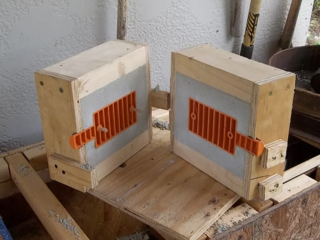
Assemble Mold
- Align registration features
- Clamp securely (rubber bands, clamps, vise)
- Ensure mold is level and stable
Prepare Casting Material
Follow material-specific instructions:
- Wax: Melt to recommended temperature (70-90°C)
- Resin: Mix thoroughly according to manufacturer ratios
- Metal: Melt to proper temperature (below mold limit)
Pouring
- Pour steadily, avoiding turbulence
- Fill until material appears in vents
- For vacuum casting, place assembled mold in vacuum chamber
- For pressure casting, apply pressure after pouring
Curing/Cooling
- Allow sufficient time for complete solidification
- Follow material-specific cure times
- Do not demold prematurely (warpage risk)
Step 6: Demolding and Finishing
Open Mold
- Carefully separate halves
- Use gentle prying if needed (avoid damaging mold)
- Remove casting
Remove Flash
- Trim excess material at parting line
- Cut off sprue and vents
- Sand/grind as needed
Mold Maintenance
- Clean mold surfaces immediately
- Remove any residue
- Store properly for next use
- Inspect for wear before each use
Common Applications and Real-World Examples
Jewelry Making
3D printing lost-wax patterns has become standard practice. Designers create intricate rings, pendants, and earrings in CAD, print in castable resin, and cast directly in precious metals .
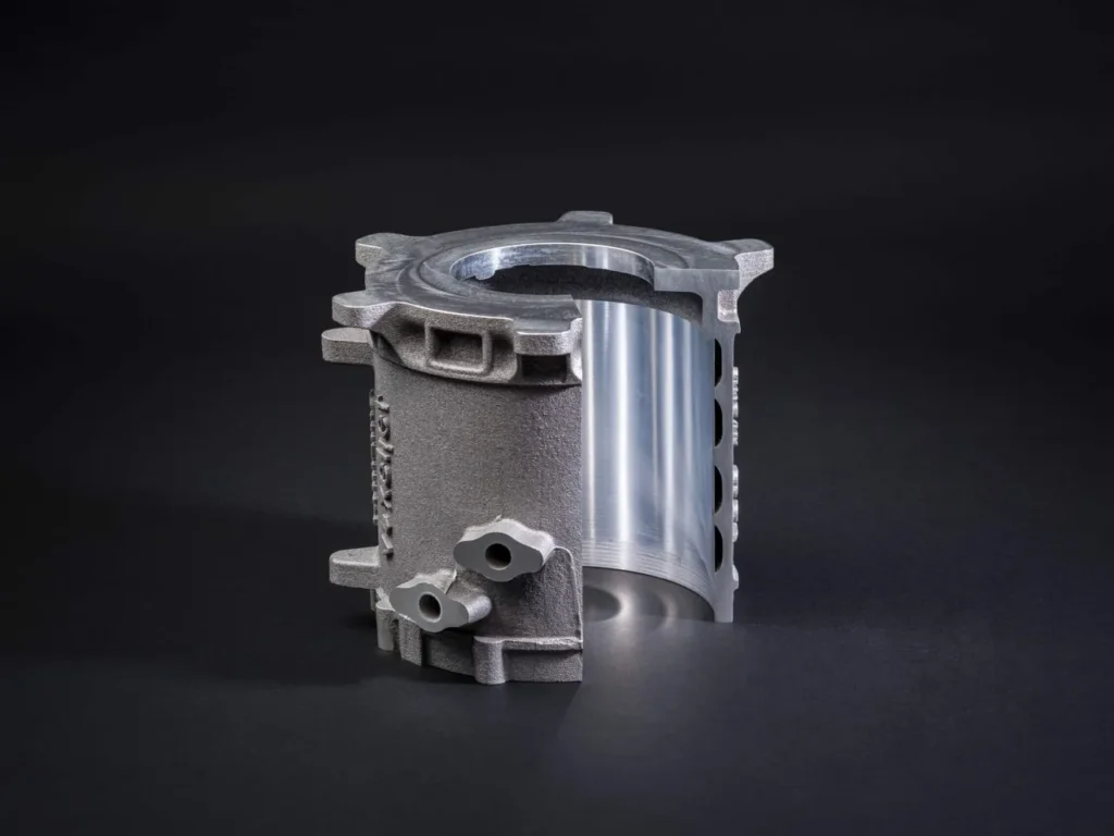
Industrial Components
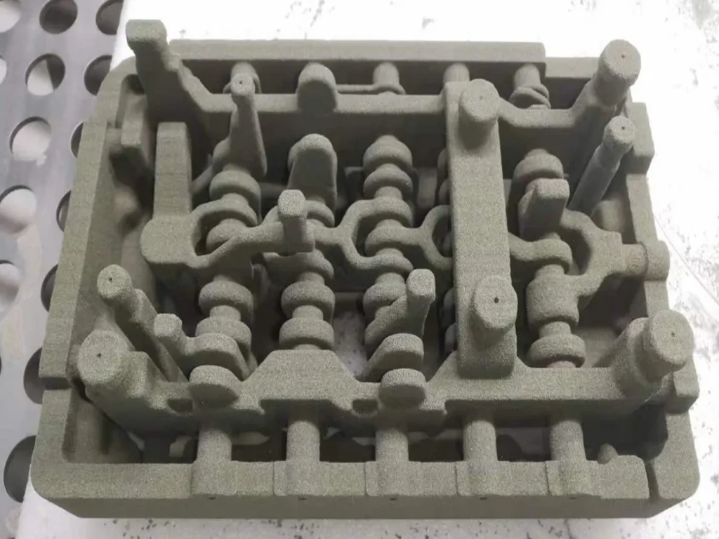
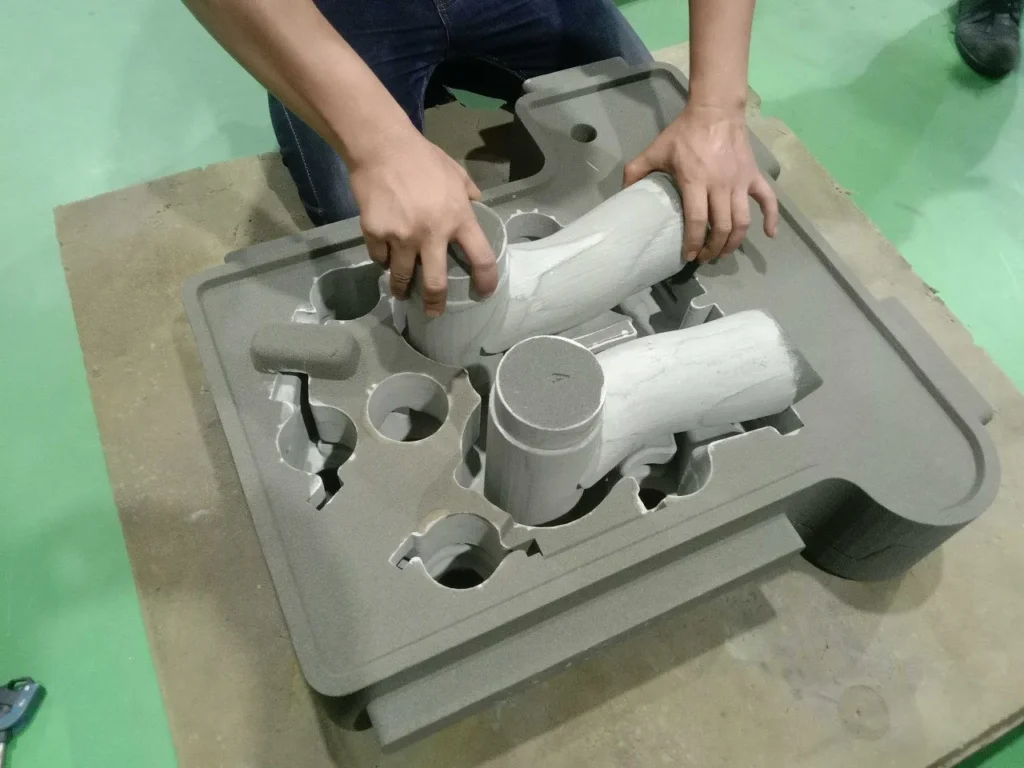
Researchers at the University of West Bohemia successfully used MJF-printed PA12-GF patterns to create sand molds for grey cast iron turbine inlet cones.
The 3D-printed approach reduced delivery time by up to 50% compared to traditional wooden patterns .
Art and Sculpture
Artists use 3D-printed molds for reproducing detailed sculptures in bronze, aluminum, or resin.
Designer Eliza Wrobel created disposable PVA molds for Egyptian-themed figures—the PVA dissolved completely in water after casting, revealing intricate details .
Low-Volume Production
Small manufacturers use 3D-printed injection molds for short runs of plastic parts (typically 10-100 pieces), avoiding the high cost of steel tooling .
Troubleshooting Common
| Problem | Likely Cause | Solution |
|---|---|---|
| Cast part sticks in mold | Insufficient draft angle, no release agent | Add draft angles, apply mold release |
| Surface roughness | Layer lines visible, insufficient post-processing | Sand mold cavity, use smaller layer height, consider vapor smoothing |
| Incomplete fill | Poor venting, material too cold | Add vents, preheat mold, adjust pouring technique |
| Porosity in cast metal | Trapped air, moisture | Improve venting, ensure materials are dry |
| Pattern cracks during burnout | Walls too thick, heating too rapid | Reduce wall thickness (0.5-1.0 mm ideal), follow recommended burnout schedule |
| Mold fails during casting | Material temperature limit exceeded | Use higher-temperature material, reduce pour temperature |
3D Printing Molds for Casting Cost Considerations
The economics strongly favor 3D printing for certain scenarios :
3D printing is more cost-effective when:
- You need 1-100 parts (prototyping, custom work)
- Design iterations are expected
- Part geometry is complex (undercuts, internal channels)
- Time to market is critical
Traditional methods are more cost-effective when:
- You need 10,000+ identical parts
- The material must be hardened tool steel
- Production timeline is long enough to amortize tooling
Real-World Example: A 3D-printed mold might cost $50-500 and be ready in 2 days, while a steel mold for the same part could cost $5,000-50,000 and take 8-12 weeks .
Conclusion
Creating 3D-printed molds for casting represents a perfect marriage of ancient technique and modern technology.
By following the steps outlined in this guide—careful CAD design, appropriate material selection, precise printing, and proper post-processing—you can create complex, high-quality castings that would be prohibitively expensive or impossible with traditional methods alone.
Whether you’re a jeweler crafting unique pieces, an engineer prototyping new products, or an artist bringing visions to life in metal, 3D-printed molds offer unprecedented design freedom, speed, and cost-effectiveness.
The technology continues to evolve, with new materials and printing methods constantly expanding the possibilities.