Metal casting is one of the oldest and most widely used manufacturing processes, allowing molten metal to be shaped into complex and precise parts. At the heart of every successful metal casting operation is a properly made mold.
How to make mold for casting metal, you first create a pattern—a replica of the desired metal part, usually made from wood, plastic, or metal.
This pattern is then pressed into a fine sand mixture (or a refractory material like plaster or ceramic) contained in a two-part frame called a flask.
After removing the pattern, a hollow cavity remains. Channels called runners and a riser are cut into the sand to allow molten metal to flow in and gases to escape.
The two halves of the mold are reassembled, and the cavity is ready to be filled with molten metal. Once the metal solidifies, the sand mold is broken away to reveal the final casting.
What Is Mold for Casting Metal?
In metal casting, a mold is a precisely formed hollow cavity that defines the external shape and key features of a metal part.
During the casting process, molten metal is introduced into this cavity, where it fills the mold, cools, and solidifies.
Once solidification is complete, the mold is opened or broken away, and the finished metal casting is removed.
Metal casting involves heating metal until it becomes liquid, then pouring or forcing it into a mold.
The metal flows into the mold cavity, takes the exact shape of the cavity as it solidifies, and forms a near-net-shape component.
While this basic principle applies to all casting processes, the most important variables include the mold material (such as sand, ceramic, wax-based shells, or metal molds)
And the method used to deliver the molten metal, which may involve gravity pouring, pressure die casting, vacuum-assisted casting, or centrifugal casting.
Regardless of the specific casting method used, molds must meet several critical engineering requirements:
- Withstand high temperatures without degrading or deforming when exposed to molten metal
- Maintain dimensional accuracy to ensure the final casting meets design specifications
- Allow controlled metal flow and cooling, minimizing defects such as porosity, shrinkage, or incomplete filling
- Release the casting without damage, either through mold separation or mold destruction
Foundation of Mold for Casting Metal
Before you can make a mold, you need a pattern. A pattern is a full-size model of the desired casting. It is used to create the mold cavity, which is the negative impression of the desired casting.
The pattern is placed in a mold box (flask), and molding material is packed around it. The pattern is then removed, leaving behind the mold cavity. The mold cavity is then filled with molten metal, which solidifies to form the casting.
Pattern Materials
The material used for the pattern depends on the size and complexity of the casting, as well as the type of metal being cast and the production volume:
- Wood: Inexpensive and easy to work with, suitable for prototypes and low-volume production. However, wood can warp over time when exposed to moisture.
- Metal (Aluminum, Cast Iron, Steel): Very durable and dimensionally accurate, suitable for high-volume production. Metal patterns are more expensive and require specialized machining.
- Plastics/Polymers (Epoxy, Urethane): Good durability and detail, often cheaper than metal, suitable for moderate volumes.
- 3D Printed Materials: Used for rapid prototyping and increasingly for direct mold/core production, enabling complex geometries and fast iteration.
Pattern Allowances: Critical Design Factors
Patternmaking is far more than making an exact replica of the shape you want to cast. The patternmaker must account for the mold type and casting metal characteristics through carefully calculated allowances built into the pattern:
Shrinkage (Contraction) Allowance: All metals used for casting shrink after solidification in the mold. The pattern must be made larger than the required casting by an amount equal to the shrinkage of the specific metal from its melting point to room temperature. Typical shrinkage allowances for common casting metals include:
- Gray cast iron: 7 to 10.5 mm/m
- Steel: 20 mm/m
- Aluminum: 18 mm/m
- Aluminum alloys: 13 to 16 mm/m
- Brass: 14 mm/m
- Bronze: 10.5 to 21 mm/m
Draft Allowance: The pattern needs to be removed from each mold it shapes without breaking or distorting it. Draft is a taper that facilitates pattern removal.
A general rule of thumb is to add a draft of about 1–3 degrees on vertical surfaces, though the exact angle depends on the complexity of the pattern, the mold type, and the surface type.
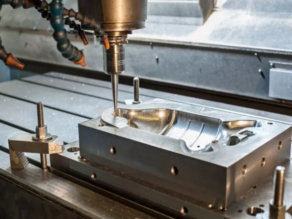
Machining Allowance: Some castings are finished by machining. Patterns for machine-finished castings intentionally include excess material to compensate for material that will be lost in the finishing stage.
Distortion Allowance: Patterns may be intentionally distorted to compensate for expected cooling distortion.
How to Make Sand Mold for Metal Casting
Sand molding is one of the most accessible and widely used casting methods, accounting for over 70% of all castings produced worldwide. Sand molds are typically single-use, cost-effective for low to medium volumes, and widely used for iron, aluminum, and steel castings.
Sand Mold Materials
The sand used for molding is not ordinary beach sand. It is a specially engineered mixture that must possess several key properties: permeability to allow gases to escape, strength to hold its shape, and refractoriness to withstand high heat without breaking down.
Common sand mold types include:
- Green Sand: A mixture of silica sand, bentonite clay (a binder), water, and sometimes additives. It is called “green” because it contains moisture (typically 3–6%). Green sand is inexpensive and reusable, but produces a rougher surface finish. For most sand casting projects, the recommended ratio is about 100 parts silica sand to 6 parts bentonite clay by weight.
- Resin-Bonded Sand (No-Bake/Airset): Sand mixed with synthetic resins (phenolic, furan) hardened by heat or catalysts. Provides better dimensional accuracy and surface finish than green sand, with tolerances consistently achieving ±0.25 mm.
- Sodium Silicate (CO₂) Sand: Sand bonded with sodium silicate, hardened by passing CO₂ gas. Fast production and good accuracy.
- Shell Molding: Fine sand coated with a thermosetting phenolic resin is heated against a metal pattern to form a thin, hard shell. Excellent surface finish and dimensional accuracy for medium volumes.
Step-by-Step Sand Mold Making Process
Step 1: Prepare the Pattern and Flask
The flask is a two-part frame that holds the sand. The bottom half is called the drag, and the top half is called the cope. Clean the pattern thoroughly and apply a release agent to make it easier to remove from the sand later.
Step 2: Prepare the Drag
Place the pattern on a flat board inside the drag, centered and positioned properly. Dust the pattern with parting powder (talc or graphite) to prevent sand from sticking.
Step 3: Pack the Sand
Fill the drag with sand in layers. Start by sifting a thin layer of fine sand directly onto the pattern to capture fine details. Add sand in approximately 2-inch layers rather than dumping it all at once. Use a rammer to compress each layer firmly, starting gently around the pattern to avoid shifting it, then packing harder as you build up. The sand should feel firm like packed brown sugar, not loose.
Step 4: Create Vents
Insert vent wires at regular intervals while packing the sand. These create small channels that allow steam and gases to escape during pouring, preventing bubbles in your casting.
Step 5: Flip and Prepare the Cope
Once the drag is full, use a straight edge to scrape off excess sand level with the top of the flask. Place a board on top and carefully flip the entire drag over. Your pattern is now facing up, ready for the cope half.
Step 6: Create the Gating System
Mark sprue and riser locations. The sprue is where you pour metal in, and risers are reservoirs that feed extra metal as the casting shrinks.
Place the sprue near the thickest part of the pattern. Cut small funnel-shaped depressions and insert sprue pins. Carve runners and gates connecting the sprue to the pattern cavity.
Step 7: Pack the Cope
Place the cope on top of the drag. Fill with sand in layers, compacting each layer thoroughly. Once full, level the sand and create a pouring basin around the sprue.
Step 8: Remove the Pattern
Separate the cope from the drag. Carefully remove the pattern from the drag, taking care not to damage the sand cavity. Smooth any rough edges. Cut a pouring cup at the top of the sprue.
Step 9: Close the Mold
Reassemble the cope and drag, ensuring proper alignment. The mold is now ready for metal pouring.
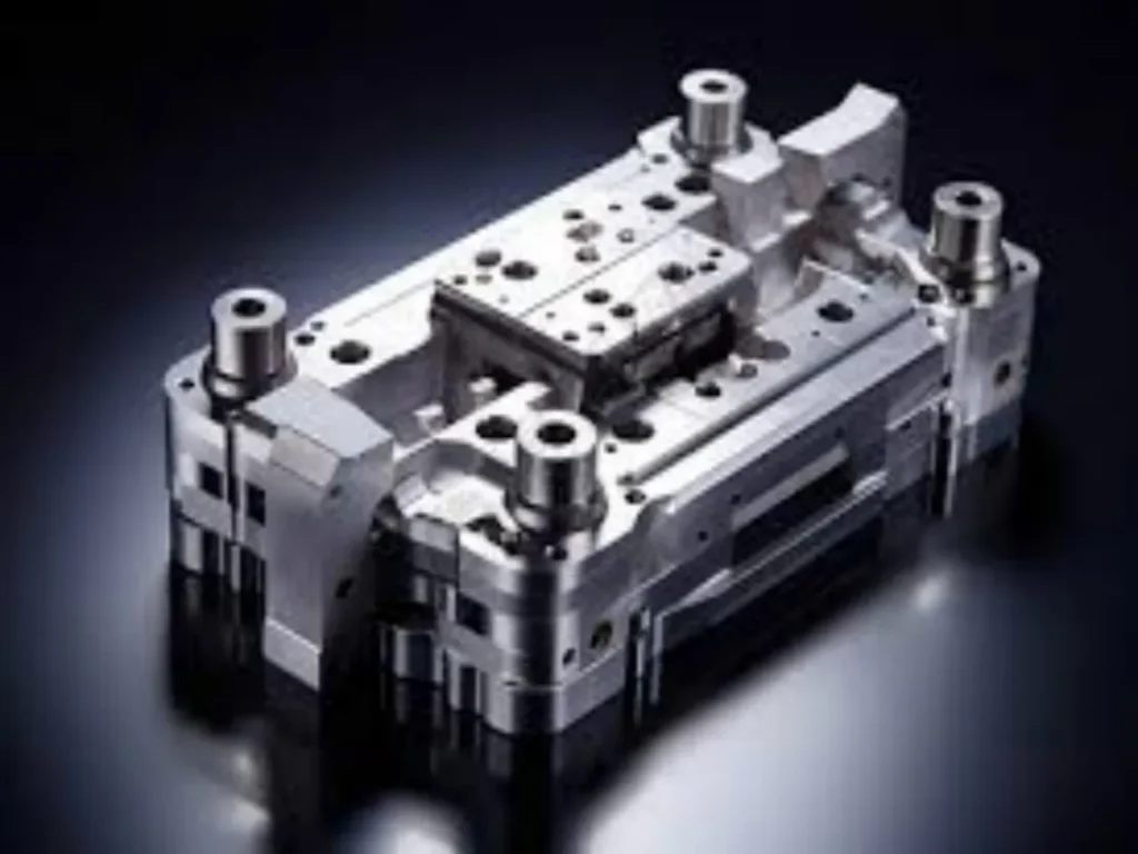
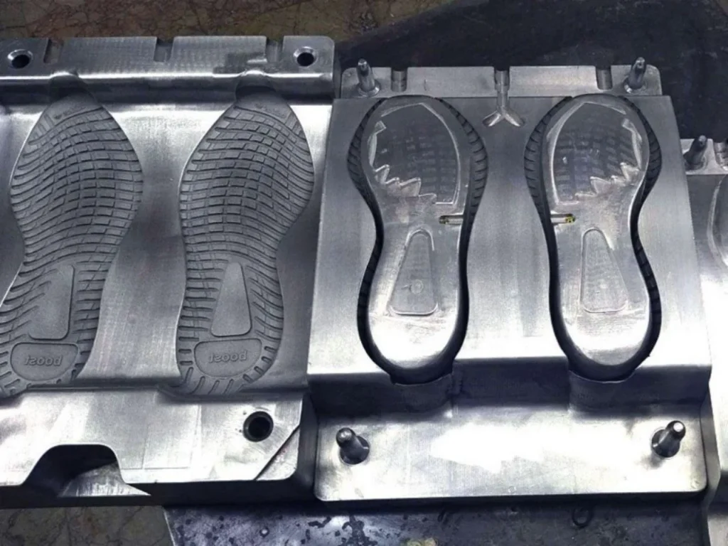
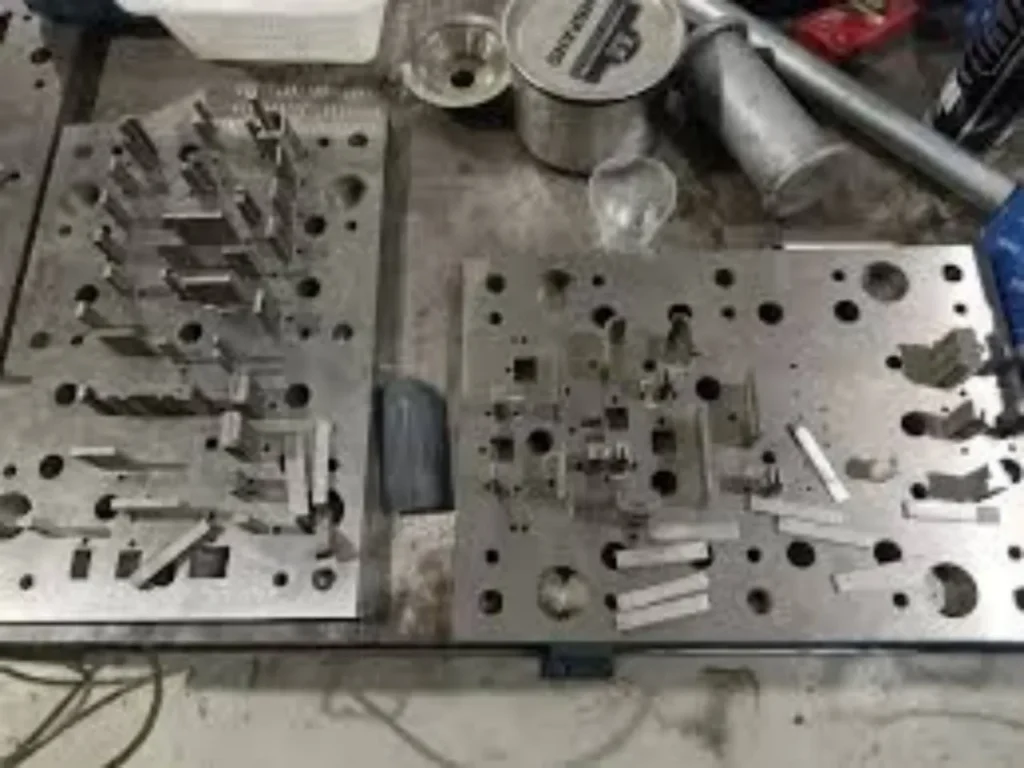
Permanent Metal Molds
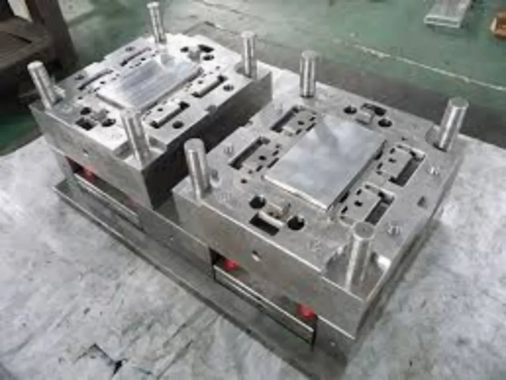
Permanent molds are reusable metal molds, typically made from steel or cast iron, used for high-volume production. They are common for aluminum and magnesium casting.
In permanent mold casting, molten metal is poured (by gravity or low pressure) into a preheated metal mold. The mold’s reusability drives efficiency and consistency over a production run.
Permanent mold casting offers several advantages over sand casting:
- Superior surface finish due to the smooth metal mold surface
- Higher dimensional accuracy and tighter tolerances due to mold rigidity
- Faster cooling rates leading to refined microstructure and enhanced mechanical properties
However, the production of metal molds is more expensive, making this method less cost-effective for low-volume production. Permanent molds typically cost $25,000–$100,000 but can be used for thousands of casting cycles, making them economical for medium to high volumes.
Lost Foam Casting
Lost foam casting uses a polystyrene foam pattern that is left in the sand mold. When molten metal is poured, the foam pattern is gasified (vaporized) by the thermal energy of the metal, leaving a precise cavity that exactly replicates the original pattern.
The pattern is typically molded from expanded polystyrene (EPS), which is approximately 97.5% air. For small volume runs, the pattern can be hand-cut or machined from a solid block of foam. For larger volumes, patterns are molded in aluminum tooling.
This process eliminates the need for pattern removal, core assembly, and parting lines, making it ideal for complex geometries that would be difficult or impossible with conventional sand casting.
3D Printed Sand Molds and Cores
Additive manufacturing has revolutionized mold making for metal casting. Technology for 3D printing sand molds and cores is well developed and has gained significant traction in recent years.
In this process, a digital CAD model of the part is used to design the mold and core geometry, including gating systems. Specialized 3D printers (using binder jetting technology) build sand molds and cores layer by layer from fine quartz sand bonded with a binder. Once printed, the molds are cleaned, cured, and used for metal pouring.
The benefits of 3D printed sand molds include:
- No permanent tooling required—molds can be printed directly from CAD
- Enables complex geometries that were previously unfeasible, including undercuts and bionic geometries
- Shortens lead times from weeks to days (molds can be printed in 24–48 hours)
- Ideal for prototyping, iterative design, and low-volume production (1–100 pieces)
- Reduces setup time and eliminates the need for complex core assemblies
Typical dimensional tolerances for 3D printed sand mold castings are ±0.045 inches per inch, with surface finish ranging from 200–420 RMS.
Minimum wall thickness is approximately 0.250 inches (6.35 mm), and typical part weights range from 2 to 400 lbs.
Choosing the Right Mold Type
Selecting the appropriate mold-making method depends on several factors. The table below provides a comparison of the most common approaches:
| Factor | Sand Casting (Green Sand) | Resin-Bonded (No-Bake) | Permanent Mold | Investment Casting | 3D Printed Sand |
|---|---|---|---|---|---|
| Mold Cost | Low | Medium | High ($25K–$100K) | Medium-High | Low (no tooling) |
| Tooling Lead Time | 1–4 weeks | 2–5 weeks | 6–12 weeks | 4–8 weeks | Days |
| Production Volume | Low to Medium | Low to Medium | Medium to High | Low to High | Prototype to Low |
| Surface Finish (Ra μin) | 500–1000 | 250–500 | 150–300 | 125–250 | 200–420 |
| Dimensional Tolerance (±) | ±0.5 mm | ±0.25 mm | ±0.1 mm | ±0.05 mm | ±0.045 in/in |
| Part Size Range | Ounces to tons | Ounces to 500+ kg | Small to Medium | Small to Medium | 2–400 lbs |
| Typical Applications | Engine blocks, housings | Industrial pumps, valve bodies | Auto wheels, gear housings | Aerospace, jewelry, medical | Prototypes, complex parts |
| Metals | All castable metals | All castable metals | Non-ferrous primarily | All castable metals | All castable metals |
General Selection Guidelines
Choose Sand Casting (Green Sand) when:
- You need low to medium production volumes (1–1,000+ parts)
- Parts are large (from ounces to several tons)
- Budget constraints are significant
- Surface finish and tight tolerances are not critical
- You require design flexibility for frequent changes
Choose Permanent Mold Casting when:
- Production volumes are high (thousands to millions of parts)
- You need consistent dimensional accuracy and good surface finish
- Parts are primarily aluminum, magnesium, or copper alloys
- You can justify the high initial tooling investment
Choose Investment Casting when:
- Exceptional surface finish and tight tolerances are required
- Parts are complex with undercuts and fine details
- Production volumes are moderate to high
- You need near-net-shape parts with minimal post-machining
Choose 3D Printed Sand Molds when:
- You need rapid prototypes or low-volume production (1–100 parts)
- Part geometries are complex with internal channels or undercuts
- You want to avoid permanent tooling investment
- Short lead times are critical (days rather than weeks)
- Design iterations are expected before finalizing production tooling
Conclusion
Making a mold for metal casting is a multi-step process that begins with a carefully designed pattern incorporating critical allowances for shrinkage, draft, and machining.
Whether you choose sand casting for its low cost and versatility, investment casting for precision and surface finish, permanent mold casting for high-volume efficiency, or 3D printed sand molds for rapid iteration and complex geometries
The fundamental principles remain the same: create a precise cavity, deliver molten metal through an optimized gating system, and ensure controlled cooling for defect-free castings.
The right mold-making method depends on your specific production requirements: part size and complexity, material selection, production volume, dimensional tolerances, surface finish specifications, and budget constraints.
By understanding the strengths and limitations of each approach, you can select the optimal mold-making strategy for your project and achieve consistent, high-quality metal castings.