Structural foam molding is a highly effective manufacturing process that produces lightweight, durable plastic parts with a solid outer skin and a cellular core.Structural Foam Molding Troubleshooting is also a crucial aspect.
By introducing a blowing agent into the polymer melt, this method achieves significant weight reduction while maintaining excellent stiffness-to-weight ratios.
However, like any sophisticated manufacturing process, structural foam molding can encounter a range of defects that compromise product quality, increase scrap rates, and drive up production costs.
What is Structural Foam Molding
Structural Foam Molding is a low-pressure plastic injection molding process used to produce large, rigid, and lightweight parts with a cellular core and solid skin. Unlike conventional injection molding, which creates fully solid parts, structural foam molding introduces a chemical blowing agent or physical gas (usually nitrogen or carbon dioxide) into the molten plastic. As the material fills the mold, the gas expands, creating a foam-like internal structure while the surface remains solid.
This process is ideal for parts that require high strength-to-weight ratios, dimensional stability, and thick walls without sink marks – common challenges in standard injection molding.
How It Works
- Material Preparation: Plastic resin (typically polypropylene, ABS, polystyrene, or polycarbonate) is mixed with a chemical blowing agent (CBA) or fed into a machine equipped for physical gas injection (e.g., MuCell technology).
- Plasticization and Gas Activation: The mixture is heated in the injection barrel. The blowing agent decomposes (for CBA) or the dissolved gas comes out of solution (for physical gas), forming tiny bubbles of inert gas within the molten polymer.
- Low-Pressure Injection: The melt, containing gas bubbles, is injected into the mold cavity at a much lower pressure (typically 1,000–4,000 psi) compared to conventional injection molding (10,000–30,000 psi). The mold is only partially filled – typically 70–95% full.
- Foaming and Expansion: As the gas-saturated melt enters the cavity, the pressure drop causes the dissolved gas to expand rapidly. This expansion pushes the melt to completely fill the mold. The gas bubbles migrate toward the hotter interior, leaving a compacted, solid layer at the cooler mold walls.
- Cooling and Ejection: The part cools, with the solid skin forming first and the cellular core solidifying last. The result is a part with a dense, smooth surface and a porous, foam-like interior.
Key Characteristics
| Feature | Description |
|---|---|
| Internal Structure | Solid skin + cellular core (like a honeycomb or sponge) |
| Injection Pressure | Low (1,000–4,000 psi) |
| Clamp Force | Low (requires smaller, less expensive presses) |
| Part Weight | 10–30% lighter than solid injection molded parts |
| Wall Thickness | Can be uniform or variable, typically 0.25–0.5 inches (6–13 mm) or more |
| Surface Quality | May exhibit a characteristic “swirl” pattern (cosmetic issue) |
Major Advantages
- Lightweighting: The cellular core reduces density by 10–30% without significant loss of stiffness (rigidity is proportional to thickness³, so a thicker foam part can be stiffer than a thinner solid part of the same weight).
- Dimensional Stability: Thick sections are free of sink marks because the foaming action compensates for shrinkage. This allows for thick ribs and bosses without surface defects.
- Lower Clamp Tonnage: Since injection pressure is low, SFM can be run on smaller presses than conventional molding for the same projected area. This reduces capital and operating costs.
- Stress Reduction: Low-pressure filling minimizes molded-in stresses, resulting in less warpage and better flatness.
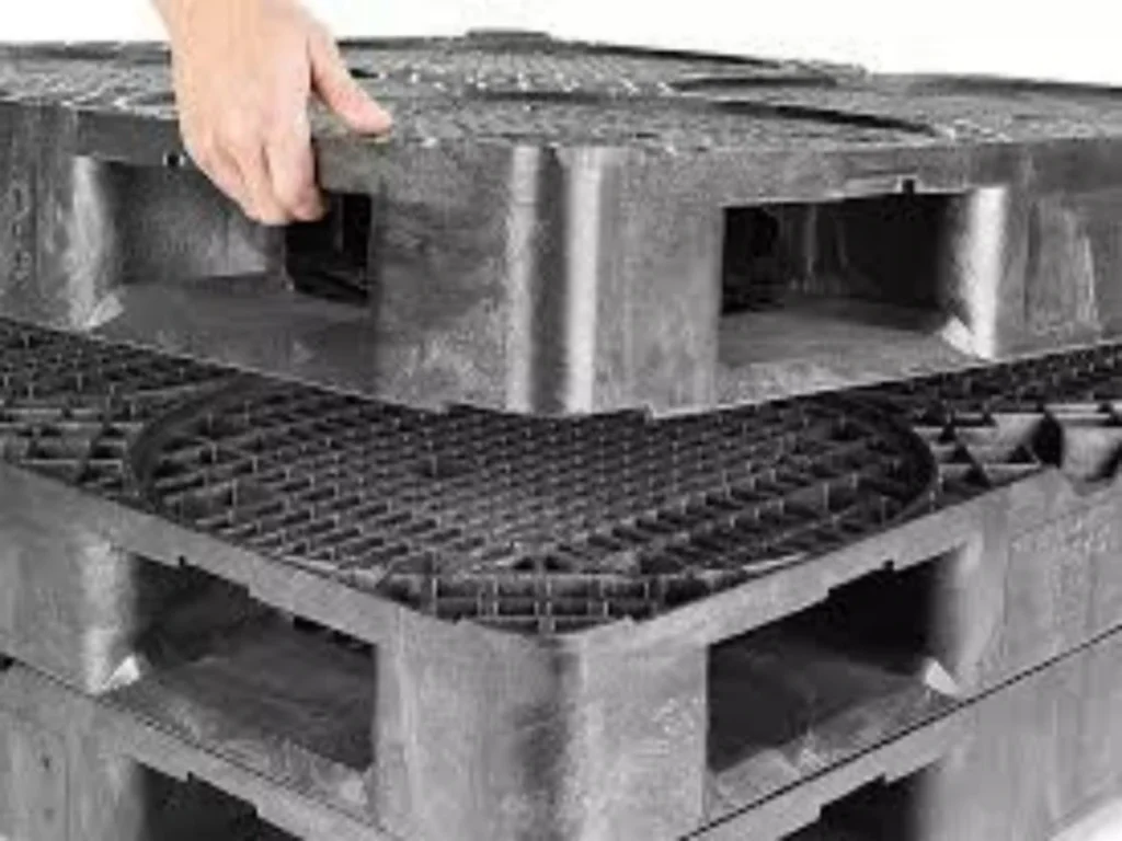
- Longer Flow Lengths: The foaming melt has lower viscosity and can flow through long, thin sections, making it suitable for large parts like pallets, enclosures, and automotive panels.
Common Disadvantages
- Surface Swirl: The expanding gas can cause a visible mottled or swirl pattern on the surface. This is often acceptable for structural parts but may require painting or a secondary operation for cosmetic applications.
- Lower Surface Hardness: The solid skin is relatively thin, so the surface may be more prone to scratching than a solid molded part.
- Not for Small or Thin Parts: SFM excels at large, thick parts. Small parts or thin walls (<0.125 in / 3 mm) provide insufficient space for the foam core to develop.
- Mechanical Properties: While stiffness-to-weight ratio is excellent, tensile strength and impact resistance are generally lower than solid injection molded parts.
Typical Applications
Because of its ability to produce large, flat, warp-resistant parts with thick sections, structural foam molding is widely used in:
- Industrial Enclosures: Large printer housings, medical device casings, electrical cabinets.
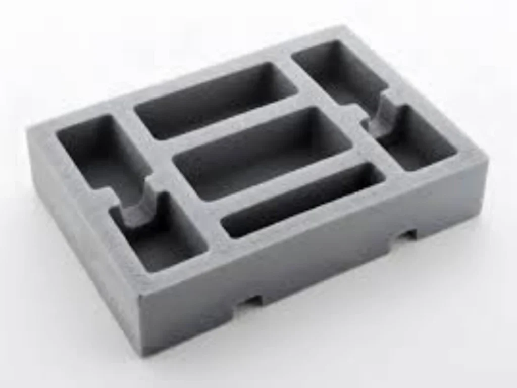
- Material Handling: Pallets, containers, totes, and dunnage trays.
- Automotive: Instrument panels, door trim substrates, armrests, and underbody shields.
- Furniture: Chair shells, table bases, and outdoor benches.
- Construction & Infrastructure: Manhole covers, cable spools, and trench drains (often using recycled plastics).
Structural Foam vs. Conventional Injection Molding
| Parameter | Structural Foam Molding | Conventional Injection Molding |
|---|---|---|
| Part internal structure | Cellular core + solid skin | Fully solid |
| Injection pressure | Low (1,000–4,000 psi) | High (10,000–30,000 psi) |
| Clamp force required | Low | High |
| Maximum part size | Very large (several square feet) | Limited by press tonnage |
| Sink marks on thick sections | None | Severe |
| Surface appearance | May have swirl pattern | Smooth, glossy |
| Typical wall thickness | 0.25–0.5 in (6–13 mm) | 0.04–0.16 in (1–4 mm) |
The 10 Most Common Problems in Structural Foam Molding
Surface Swirls / Flow Marks
Definition and Appearance: Surface swirls are the most common visual defect in structural foam parts.
They manifest as spiral, wavy, or irregular silvery streaks, appearing primarily near the gate or at the end of the melt flow path.
Root Causes: The blowing agent nucleates and expands prematurely at the melt flow front. When these bubbles migrate to the mold surface, they rupture, leaving behind chaotic flow marks.
Excessively high mold temperatures delay the solidification of the surface skin, thereby exacerbating the swirls; conversely, excessively high injection speeds intensify turbulence, making it easier for bubbles to reach the surface.
Impact: Severely compromises the product’s aesthetic appearance, often necessitating secondary painting or texturing processes to conceal the defects, which increases post-processing costs.
Preventive Measures: Maintain mold temperature within the range of 60–90°C; employ Gas Counter-Pressure (GCP) technology (at 0.8–2.0 MPa) to suppress premature foaming; appropriately increase injection speed to facilitate rapid mold filling; and incorporate nucleating agents into materials—such as PP—to refine the cell structure.
Internal Voids
Definition and Appearance: Internal voids refer to large cavities or pores occurring within the core of a molded part.
These defects are typically invisible to the naked eye but become evident upon X-ray inspection or cross-sectioning.
Root Causes: Excessive blowing agent dosage (>1.5 wt%) leads to an accumulation of surplus gas;
insufficient holding pressure time (<5 seconds) allows bubbles to over-expand before the material stabilizes;
or the injection volume falls below 98% of the mold cavity volume, preventing adequate compensation for melt shrinkage.
Impact: Significantly reduces the part’s tensile strength, fatigue life, and structural integrity, potentially leading to internal crack propagation during service.
Preventive Measures: Control the blowing agent dosage within the range of 0.5–1.5 wt%; extend the holding pressure time to 5–12 seconds; maintain the injection volume between 98% and 102% of the mold cavity volume; and increase back pressure to 8–12 MPa to promote the uniform dispersion of the blowing agent.
Sink Marks
Definition and Appearance: Sink marks are localized depressions or pits that appear on the surface of a molded part.
They are typically located in thick-walled sections, on the reverse side of reinforcing ribs, or at points where wall thickness undergoes abrupt changes.
Root Cause: Although structural foam is more resistant to sink marks than traditional injection molding, when the wall thickness is less than 6 mm or the local geometric design is flawed, shrinkage in the core layer can still pull on the outer skin, resulting in surface depressions.
Uneven cooling exacerbates these localized shrinkage differentials.
Impact: Compromises surface flatness, negatively affects assembly fit and aesthetics, and is generally unacceptable for cosmetic parts.
Preventive Measures: Ensure a minimum wall thickness of ≥6 mm; incorporate fillets at the bases of ribs to ensure smooth transitions in wall thickness;
achieve uniform cooling (maintaining mold temperature fluctuations within ±2°C); and incorporate reinforcing ribs in unavoidable problem areas to provide surface support.
Warpage and Deformation
Definition and Manifestation: Warpage refers to the twisting, bending, or curling of a part after demolding, resulting in dimensions that deviate from the engineering drawing specifications.
Root Cause: Inconsistent cooling rates across different regions of the mold generate internal stresses; non-uniform wall thickness design; or premature demolding and unbalanced ejection forces.
While the low-stress characteristics of structural foam can mitigate warpage, severe non-uniform cooling can still lead to deformation.
Impact: Render parts unassemblable, requiring either post-molding correction or scrapping; this issue is particularly critical for large, flat panel parts.
Preventive Measures: Design conformal cooling channels to ensure uniform mold temperatures (within ±2°C);
allocate 40–60% of the total cycle time to the cooling phase; incorporate sufficient draft angles (≥1.5°); and add process ribs to large parts to resist deformation.
Short Shots
Definition and Manifestation: A short shot occurs when the molten material fails to completely fill the mold cavity, resulting in missing edges or localized incompleteness in the finished part.
Root Cause: Insufficient injection volume (less than 98% of the cavity volume); poor venting, leading to gas back-pressure that impedes flow;
molten material temperature being too low, causing premature solidification; undersized or improperly positioned gates; or insufficient injection pressure.
Impact: Directly results in defective parts that cannot be salvaged, thereby reducing overall production yield.
Preventive Measures: Precisely calculate the injection volume and maintain it within 98–102% of the cavity volume; optimize the depth (0.02–0.04 mm) and placement of vent channels;
raise the molten material temperature to the upper limit (≤230°C); appropriately increase gate dimensions; and utilize multi-point sequential injection techniques.
Scorching / Black Spots
Definition and Appearance: Scorching manifests as yellowish-brown to black burn marks on the surface or within the interior of the part, often accompanied by a burnt odor.
Root Causes: Air within the mold cavity is rapidly compressed (diesel effect), causing a sudden rise in temperature that exceeds the polymer’s decomposition temperature;
excessive melt temperature (>230°C) leads to thermal degradation; excessive material residence time; or excessively rapid decomposition of the foaming agent.
Impact: Permanent degradation of material properties; unacceptable aesthetic appearance; in severe cases, damage to the mold surface.
Preventive Measures: Reduce injection speed to minimize air compression; improve venting by adding vent channels or utilizing ejector pin clearances at locations prone to scorching;
control melt temperature to ≤230°C; and periodically clean the barrel to prevent prolonged material stagnation.
Uneven Cell Structure
Definition and Appearance: Significant variations in cell size are observed within the part’s cross-section, characterized by localized large cells, cell collapse, or an alternating distribution of dense layers and foamed layers.
Root Causes: Inadequate mixing of the foaming agent with the melt (due to insufficient back pressure); significant fluctuations in melt temperature; uneven mold cooling; or unstable injection speed.
Impact: Results in inconsistent mechanical properties, reduced stiffness, and a shortened fatigue life.
Preventive Measures: Increase back pressure to 8–12 MPa; maintain melt temperature within a stable range of 180–220°C; control mold temperature fluctuations to within ±2°C; utilize a static mixer or a dynamic mixing screw; and ensure the metering accuracy of the foaming agent.
Ejection Warpage / Mold Sticking
Definition and Appearance: The part undergoes bending, surface abrasion, or partial material adhesion to the mold surface during the ejection process.
Root Causes: Insufficient draft angle (<1.5°); rough mold surface finish; insufficient cooling time, resulting in incomplete solidification of the part; improper layout of ejector pins, leading to uneven ejection forces; or vacuum suction effects.
Impact: Generates deformed scrap parts; increases the difficulty of mold ejection; and may result in scratches or damage to the mold surface.
Preventive Measures: Design a draft angle of ≥1.5°; polish the mold surface to Ra ≤0.8 μm; extend the cooling time; arrange ejector pins uniformly; install gas-assisted ejection devices on the mold.
Insufficient Weld Line Strength
Definition and Appearance: A visible line appears at the point where two melt fronts converge, and the mechanical properties at this location are significantly lower than in other areas.
Root Causes: The melt temperature is too low at the point of convergence, resulting in poor fusion; inadequate venting causes gas to become entrapped at the joint interface; the injection speed is too slow; or gases from foaming agents interfere with the entanglement of polymer chains.
Impact: The part is prone to fracture at the weld line, severely compromising structural safety.
Preventive Measures: Increase the melt temperature, particularly in the convergence zone; add vents at the location of the weld line; optimize gate placement to ensure the melt fronts converge in a parallel manner (forming an angle >135°); and incorporate reinforcing ribs in the vicinity.
Flash (Overflow)
Definition and Appearance: Excess thin, sheet-like material extruded into the gaps at the mold parting line, around ejector pins, or between sliders.
Root Causes: Insufficient clamping force to withstand the cavity pressure; wear on the mold parting line, or gaps exceeding 0.05 mm; excessive injection pressure; or mold vent depths that are too deep (>0.05 mm).
Impact: Requires manual trimming, thereby increasing post-processing costs; flash may detach and become a source of foreign object contamination.
Preventive Measures: Ensure sufficient clamping force; regularly inspect the parting line and repair any wear; reduce the injection pressure; precisely control the depth of vent grooves to within 0.02–0.04 mm; and utilize high-strength mold steel materials.
Structural Foam Molding Troubleshooting Methodology
Precisely Define Defects: Document the defect type (swirl marks, short shots, voids, warpage, etc.), location, frequency, and associated process parameters.
Prioritize Root Cause Analysis: Follow the sequence: Design → Materials → Process → Mold.
Design: Verify wall thickness (≥6 mm), rib-to-wall ratio, and draft angles.
Materials: Confirm foaming agent dosage (0.5–1.5 wt%), dryness, and absence of contamination.
Process: Verify mold temperature (60–90°C), melt temperature (≤230°C), injection volume (98–102%), holding time (5–12 s), and back pressure (8–12 MPa).
Mold: Inspect vent depth (0.02–0.04 mm), cooling uniformity (mold temperature fluctuation within ±2°C), and gate location.
Single-Variable Adjustment: Alter only one parameter at a time and record the results to avoid confounding effects from multiple variables.
Verification and Standardization: Once an effective solution is identified, update the process procedures and material formulations, and provide training to the operators.
Preventive Maintenance: Regularly clean vents, calibrate sensors, and inspect mold parting lines to minimize defect recurrence.
Through this structured troubleshooting approach, over 80% of recurring defects can be eliminated at their root cause.
Preventive Maintenance
Preventing defects in structural foam molding requires a systematic approach encompassing three key areas: design, processing, and tooling.
Design: Ensure a minimum wall thickness of 6 mm to facilitate foam formation; the rib-to-wall thickness ratio may exceed 100%; ensure smooth transitions in wall thickness; and specify a minimum draft angle of 1.5° to facilitate part ejection.
Process Parameters: Maintain the mold temperature between 60°C and 90°C (excessively high temperatures can exacerbate surface swirl marks); keep the melt temperature at or below 230°C to prevent thermal degradation;
set the injection volume to 98–102% of the cavity volume, with a cavity pressure of 2–7 MPa; apply a holding pressure duration of 5–12 seconds;
and utilize a back pressure of 8–12 MPa to promote the uniform dispersion of the foaming agent.
The foaming agent addition level should be maintained between 0.5% and 1.5% by weight.
Tooling Engineering: Design vent depths between 0.02 mm and 0.04 mm, incorporating multi-point venting at the end of the flow path and within deep ribs;
ensure a uniform layout of cooling channels to maintain mold temperature fluctuations within ±2°C.
For components requiring high surface quality, Gas Counter Pressure (GCP) technology (0.8–2.0 MPa) may be employed to suppress premature foaming, thereby significantly improving the surface appearance.
Material Management: Thoroughly dry the raw materials to prevent moisture-induced voids or bubbles.
Identify potential risks early in the process through Design for Manufacturability (DFM) reviews and mold flow analysis.
A systematic, preventive approach is more cost-effective and efficient than post-production remediation, as it can significantly reduce common defects such as swirl marks, voids, warping, and short shots.
Conclusion
Structural foam molding troubleshooting is both a science and an art. Short shots, sink marks, warpage, surface swirl, internal voids, burn marks, blisters, black spots, uneven cells, and weak weld lines—represent the most common challenges faced by manufacturers.
Each has specific root causes and corresponding solutions, but the key to successful troubleshooting is systematic analysis: accurately identifying the defect, understanding the underlying process physics, and making targeted adjustments one variable at a time.
An experienced structural foam molding partner can easily identify issues as they arise and make the necessary adjustments so valuable time and money are not lost during the production process.
With careful attention to mold design, process parameters, material selection, and preventive maintenance, most defects can be prevented or quickly corrected.
As structural foam molding continues to evolve with advanced technologies like Gas Counter Pressure and mold-opening processes, the range of achievable surface qualities and mechanical properties continues to expand, making this versatile manufacturing process suitable for an ever-widening range of applications.