
Expanded Polypropylene (EPP) molding is a specialized manufacturing process that transforms polypropylene beads into lightweight, durable foam components through steam fusion.
Unlike conventional injection molding, EPP molding involves the expansion and fusion of beads within a closed mold cavity, making air vent design one of the most critical factors determining part quality, cycle time, and overall production efficiency.
When molten EPP material is injected into the mold cavity at high speed, the air originally present in the cavity must escape rapidly.
If the venting system is inadequate, trapped air creates back pressure that prevents complete filling, leads to surface defects, and extends cycle times.
Poor venting can add 10-15 seconds to every molding cycle and increase material waste by 8-12%.
Why Air Vent Design Matters in EPP Molding
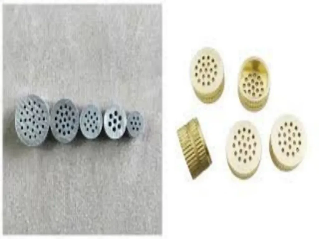
The Physics of EPP Molding
EPP molding differs fundamentally from other plastic molding processes.
The material consists of pre-expanded polypropylene beads that are injected into a mold cavity and fused together using steam.
During the filling phase, the mold cavity—which is already filled with air—must accommodate the incoming bead stream.
As the beads enter, the air must be displaced and expelled through the venting system.
The challenges are unique to EPP:
- High fill speeds require rapid air evacuation
- Complex geometries create air traps in corners, ribs, and thin sections
- Steam penetration demands balanced venting that doesn’t compromise fusion
- Bead flow behavior differs significantly from molten polymer flow
The Cost of Poor Venting
Poor venting doesn’t just create cosmetic defects—it directly impacts your bottom line:
| Problem | Consequence |
|---|---|
| Trapped air | Longer fill times (+10-15 sec/cycle) |
| Overpacking | 15-20% more material usage per shot |
| Scrap parts | 8-12% yield loss |
| Sticking parts | Press stops and manual intervention |
Manufacturers with optimized venting systems routinely achieve 99%+ yield rates, while those with poor venting struggle with scrap rates exceeding 10%.
Common Defects Caused by Poor Venting
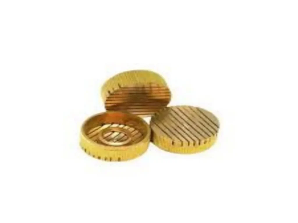
1. Incomplete Filling (Short Shots)
When air cannot escape the mold cavity quickly enough, it creates back pressure that resists the incoming EPP beads.
The result is incomplete filling, particularly in thin-walled sections and areas farthest from the injection point. For thin walls (2-4mm), poor venting leads to incomplete fusion and eventual cracking.
2. Surface Defects
Trapped air manifests on the part surface as:
- Visible bead lines where beads failed to fuse properly
- Burn marks from compressed air heating
- Surface blisters and bubbles from trapped gases
- Weld lines where flow fronts met but didn’t bond
3. Density Inconsistencies
When venting is uneven, steam distribution becomes irregular. Parts may have soft spots in some areas and overly dense regions in others, failing compression strength testing.
4. Dimensional Instability
Trapped air prevents uniform bead packing, leading to parts that warp or shrink inconsistently. For automotive applications requiring ±0.1mm tolerances, this is unacceptable.
5. Extended Cycle Times
Operators compensate for poor venting by slowing down fill rates to prevent trapped air issues. This adds seconds to every cycle—and over a year of production, those seconds translate to thousands of lost parts.
Core Principles of EPP Mold Air Vent Design
Principle 1: Vent at the Last Point of Fill
The most fundamental rule of vent design: place vents where the material flow front terminates.
As the cavity fills, air is pushed ahead of the advancing material. Vents at the end of flow paths allow this air to escape efficiently.
Principle 2: Balance Venting with Material Containment
Vents must be large enough to allow rapid air escape but small enough to prevent bead leakage.
EPP beads are lightweight and can escape through oversized vents.
The vent depth must be precisely calculated for EPP’s specific flow behavior.
Principle 3: Distribute Vents Strategically
Single-point venting is rarely sufficient for complex parts. Effective designs use:
- Primary vents at the parting line
- Secondary vents along weld lines and corners
- Tertiary vents in deep ribs and blind pockets
Principle 4: Consider Steam Flow
EPP molding relies on steam to fuse beads. Venting channels must allow not only air escape but also proper steam circulation. Over-venting can create cold spots that prevent complete fusion.
Key Design Parameters for EPP Mold Vents
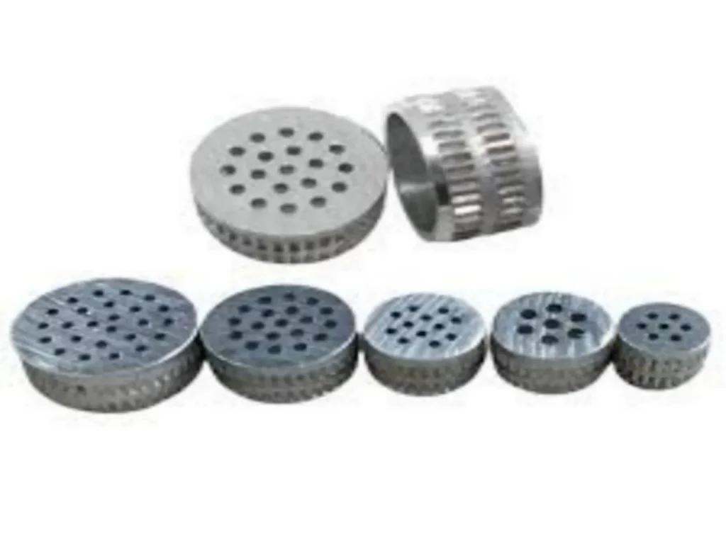
Vent Depth
Vent depth is the most critical parameter. It must be:
- Deep enough to allow rapid air evacuation
- Shallow enough to prevent EPP bead leakage
For general EPP molding, recommended vent depths typically range from 0.0010 to 0.0020 inches (approximately 0.025-0.050mm). However, the optimal depth depends on:
- Material density (15-80g/L ranges require different depths)
- Part geometry (thin sections need finer venting)
- Bead size (larger beads require slightly deeper vents)
Some references suggest EPP vent depths around 0.2-0.4mm for specific applications, but these values must be verified against your specific material and part geometry.
Vent Width
Vent width must provide sufficient cross-sectional area for air flow while preventing material escape.
Recommended widths typically range from 3-6mm, with 6.35mm or greater suggested for some applications.
For complex internal geometries, narrower vents may be used, but the total venting area must be sufficient to evacuate air at the required fill rate.
Vent Length
Vents must extend from the cavity through the mold to atmosphere. The length affects flow resistance—shorter vents provide less resistance but may be constrained by mold geometry.
Vent Spacing
The spacing between vents depends on:
- Part size and geometry (larger parts need more vents)
- Flow path length (longer paths need intermediate vents)
- Material flow characteristics (EPP’s unique behavior requires specialized spacing)
Step-by-Step Vent Design Optimization Process
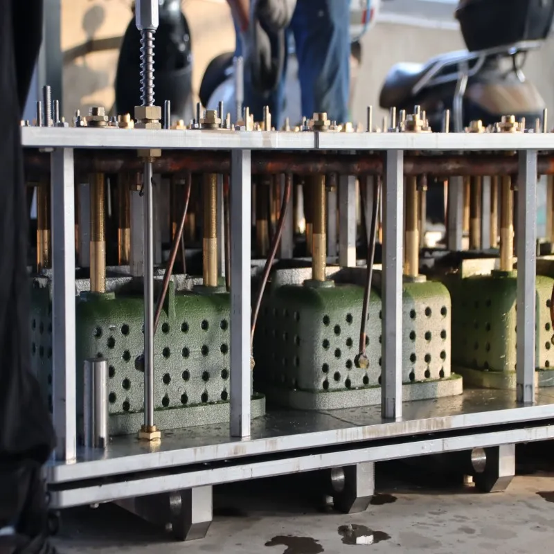
Step 1: Analyze Part Geometry
Begin by identifying all potential air trap locations:
- Deep ribs and bosses
- Thin wall sections
- Corners where flow fronts converge
- Areas farthest from the injection point
Step 2: Determine Flow Paths
Map the material flow within the cavity. The venting system must be positioned where flow fronts terminate.
Step 3: Calculate Venting Requirements
For each vent location, determine:
- Required vent depth based on material and geometry
- Vent width sufficient for air volume
- Number of vents needed for complete evacuation
Step 4: Design Primary Venting System
Place primary vents at:
- The parting line (most common location)
- The end of major flow paths
- Areas of maximum cavity depth
Step 5: Add Secondary and Tertiary Vents
For complex geometries:
- Add vents along weld lines and corners
- Include vents in blind pockets and deep ribs
- Consider multi-stage venting with graduated depths
Step 6: Validate with Simulation
Modern mold design increasingly uses flow simulation to validate vent placement before manufacturing. This identifies potential air traps that might otherwise be missed.
Step 7: Trial and Refinement
Even the best designs benefit from real-world testing:
- Run trial shots at production conditions
- Inspect parts for venting-related defects
- Adjust vent depths or add additional vents as needed
Advanced Vent Design Strategies
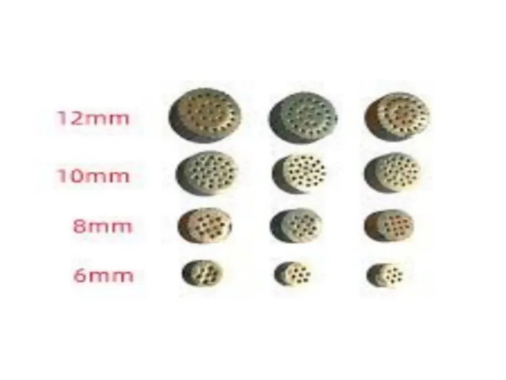
Multi-Stage Venting
Multi-stage venting uses progressively deeper vent channels. The initial, shallow section prevents bead leakage while allowing air to escape. The deeper section provides additional flow capacity when needed.
Vacuum-Assisted Venting
Some advanced EPP molding operations use vacuum systems to actively pull air from the cavity. This can dramatically reduce cycle times and improve part quality, though it adds system complexity.
3D-Printed Vent Inserts
Recent innovations include 3D-printed mold inserts with integrated venting networks.
These allow for vent placement that would be impossible with conventional machining, enabling near-contour cooling integration.
Conformal Cooling Integration
When combined with conformal cooling channels that follow part contours, optimized venting can cut cooling time by 40%. The synergy between cooling and venting is critical for high-speed production.
Material-Specific Considerations
EPP vs. EPS Venting Requirements
EPP and EPS (expanded polystyrene) have different venting needs:
| Factor | EPP | EPS |
|---|---|---|
| Steam penetration | Requires higher depth | Requires sharper edges |
| Vent edge sharpness | Less critical | More critical |
| Shrinkage behavior | Different compensation needed | Standard compensation |
A mold designed for EPS will rarely produce acceptable EPP parts.
Density Variations
EPP material densities range from 15g/L to 80g/L. Higher densities require:
- Finer venting (to prevent bead loss)
- More precise vent depth control
- Different shrinkage compensation
Overmolding Applications
For EPP overmolding (bonding EPP to fabric, plastic clips, or metal inserts), venting requirements become even more demanding.
The thermal balance must be maintained within 2°C, and venting must accommodate multiple materials with different flow characteristics.
Maintenance and Troubleshooting
Regular Vent Cleaning
EPP molding produces residue that can clog vents over time. Establish a regular cleaning schedule to maintain vent performance.
Monitoring Vent Performance
Watch for these signs that vents need attention:
- Increasing cycle times
- New surface defects appearing
- Inconsistent part weights
- Rising scrap rates
Common Venting Problems and Solutions
| Problem | Likely Cause | Solution |
|---|---|---|
| Bead leakage | Vents too deep | Reduce vent depth |
| Burn marks | Insufficient venting | Add vents or increase width |
| Short shots | Air traps | Add vents at trap locations |
| Surface defects | Uneven venting | Balance vent distribution |
Conclusion
EPP mold air vent design is not a minor detail—it is a fundamental determinant of production success. Poor venting leads to scrap, slow cycles, and frustrated customers. Optimized venting delivers:
- Faster cycle times (10-15 seconds saved per cycle)
- Lower material waste (8-12% reduction)
- Higher part quality (99%+ yield rates)
- Reduced energy costs per part
Whether you’re designing a new EPP mold or troubleshooting an existing one, investing time in vent optimization pays dividends in every subsequent production cycle.
If you have any questions regarding EPS/EPP/ETPU molds, please feel free to contact us at Transfoam; we will provide you with the perfect solution.